
Positive displacement metering system

a metering system and displacement technology, applied in the direction of volume metering, liquid/fluent solid measurement, instruments, etc., can solve the problems of inability to detect small flow, inability to accurately measure the flow rate of water, and limitations of meters,

Inactive Publication Date: 2016-12-27
CRONIN WILLIAM C +1
View PDF4 Cites 5 Cited by
  • Summary
  • Abstract
  • Description
  • Claims
  • Application Information

AI Technical Summary

Benefits of technology

The preferred embodiment of the Positive Displacement Metering System is a device that can be used with any type of water meter, regardless of its size. It monitors all flow rates through the specified water meter and records them. If the lower limit of the water meter's flow rate envelope is reached, the device will track all flow rates within that envelope. This ensures that the system accurately measures the amount of liquid passing through it. The device expands the flow rate envelope of the water meter, which helps to conserve water more efficiently. Each unit of the system contributes to water conservation in a unique way.

Problems solved by technology

Since the original water meters inception, there has always been, and continues to be, inaccuracy associated with very low water flow rates.
These meters are accurate and have served our nations communities well for many years, but these meters have limitations, they are only accurate inside a given range of flow.
While these ranges are large, and cover almost all water use, very small flow still remain undetectable to both solid state and mechanical meters.
Further, these meters have no moving parts which greatly increase their reliability.
The down side to this new technology is cost; many communities are hesitant to convert to this new technology for this reason.
These meters are inexpensive, however at lower flow ranges, they are inaccurate.
Even though the low end range of detectable flow is quite good for a solid state meter, a large amount of water can still pass by the meter undetected.
The revenue lost for water utility's using mechanical meters is significantly worse.
This inability to record flow results in a significant loss of revenue for the utility.
For years, the insurance industry, home owners and businesses have incurred millions of dollars in losses due to unnecessary water damage.
Typically the damage done is created by a small leak (such as a pinhole leak inside of a wall or slab) or a catastrophic failure in a pressurized pipe network (a burst pipe or washing machine hose failure).
Both work well, but have large drawbacks, namely cost and the inability to detect very low rates of water flow, (neither unit can accurately measure, nor detect small flow rates, thus the existing units have no way of accurately measuring the amount of water leaked into the structure).

Method used


Image

  • Positive displacement metering system
  • Positive displacement metering system
  • Positive displacement metering system

Examples


example 1

A Leaking Faucet Inside the Property being Monitored

[0321]With reference to FIG. 14A, as soon as the leak begins, Piston 32 will move away from the A1 position. The water in front of the piston is feeding the leak. When the piston reaches S1, a timer begins, this is the start of T1 time. 15 minutes later, Piston 32, reaches S2, and T1 time stops. T1 time is now equal to 15 minutes. With reference to FIG. 14B, note that the T1 time of 15 minutes falls between the X value of 30 seconds and the Y value of 24 minutes. Therefore Small Leak logic will be assigned to this water event.

example 2

A Faucet Inside the Property being Monitored is Opened

[0322]With reference to FIG. 14A, as soon as the faucet is opened and water begins flowing, Piston 32 immediately moves off of A1. When the piston reaches S1, T1 time begins, 6 seconds pass and the piston reaches S2. T1 time is now equal to 6 seconds. With reference to FIG. 14B, note that the T1 time of 6 seconds is less than the value of X, 30 seconds. Therefore Standard Use logic will be assigned to this water event. At this point, the PV will open, and T2 time will begin.

example 3

A Leaking Faucet Inside the Property being Monitored is Opened

[0323]With reference to FIG. 14A, as soon as the leak begins, Piston 32 will move away from the A1 position. The water in front of the piston is feeding the leak. When the piston reaches S1, T1 time will begin. 5 minutes pass and the piston is halfway between S1 and S2, at this point, the leaking faucet is opened, and the piston immediately moves from its present position to S2 and produces a T1 time of 5 minutes and 3 seconds. With reference to FIG. 14B, notice that a T1 time of 5 min 3 seconds falls inside of the Small Leak logic sequence, but we know this is incorrect, as the leaking faucet was opened, hence Standard Use logic must apply. When we look at the OR1 sensor, we see that it measured a time value less than 2 seconds, and therefore, the T1 time value of 5 min and 3 seconds will be overridden by OR1 time. Now Standard Use logic will be assigned to this water event, rather than Small Leak logic, as OR1 time was ...


PUM


Abstract

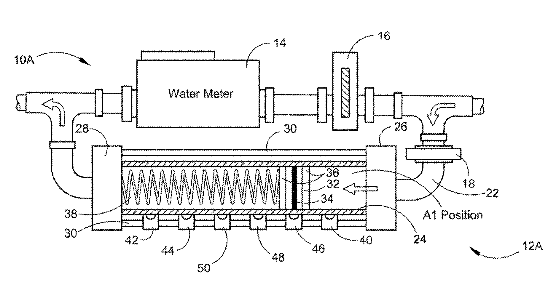
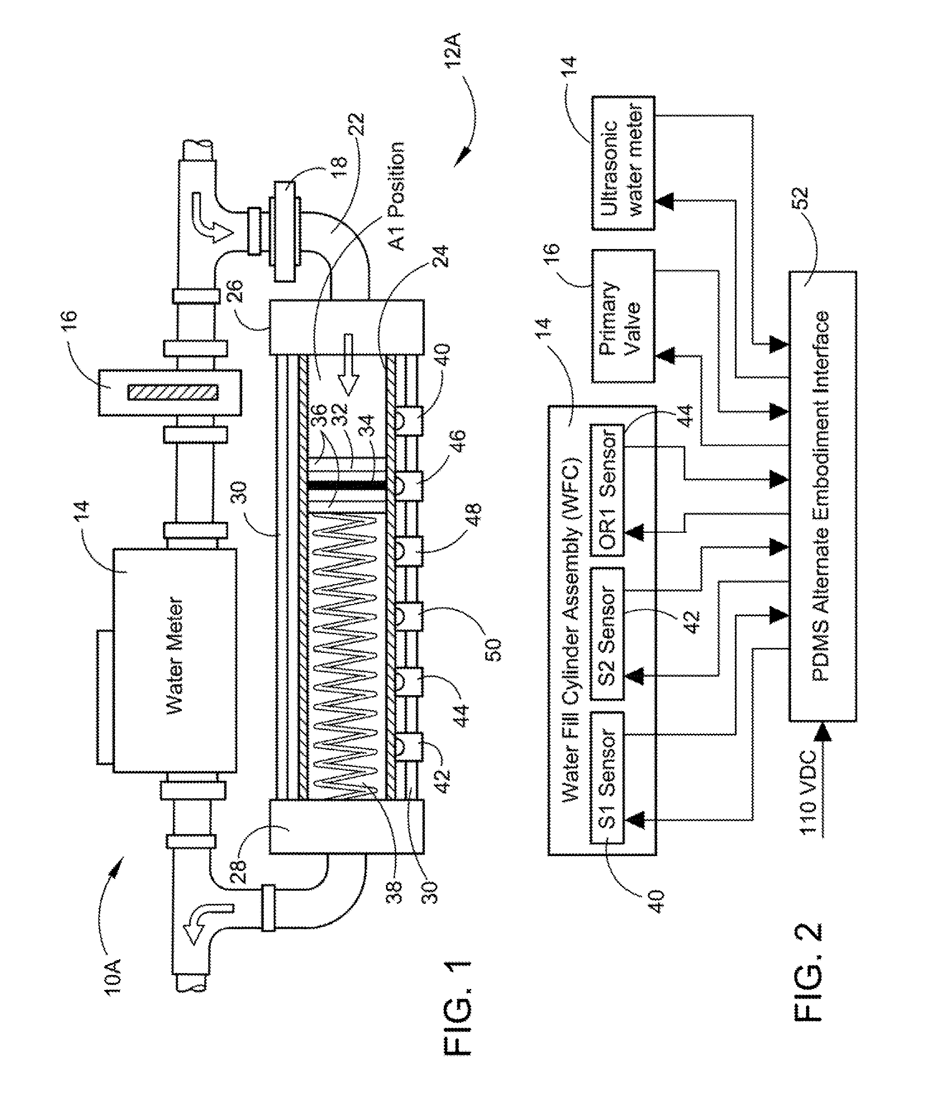
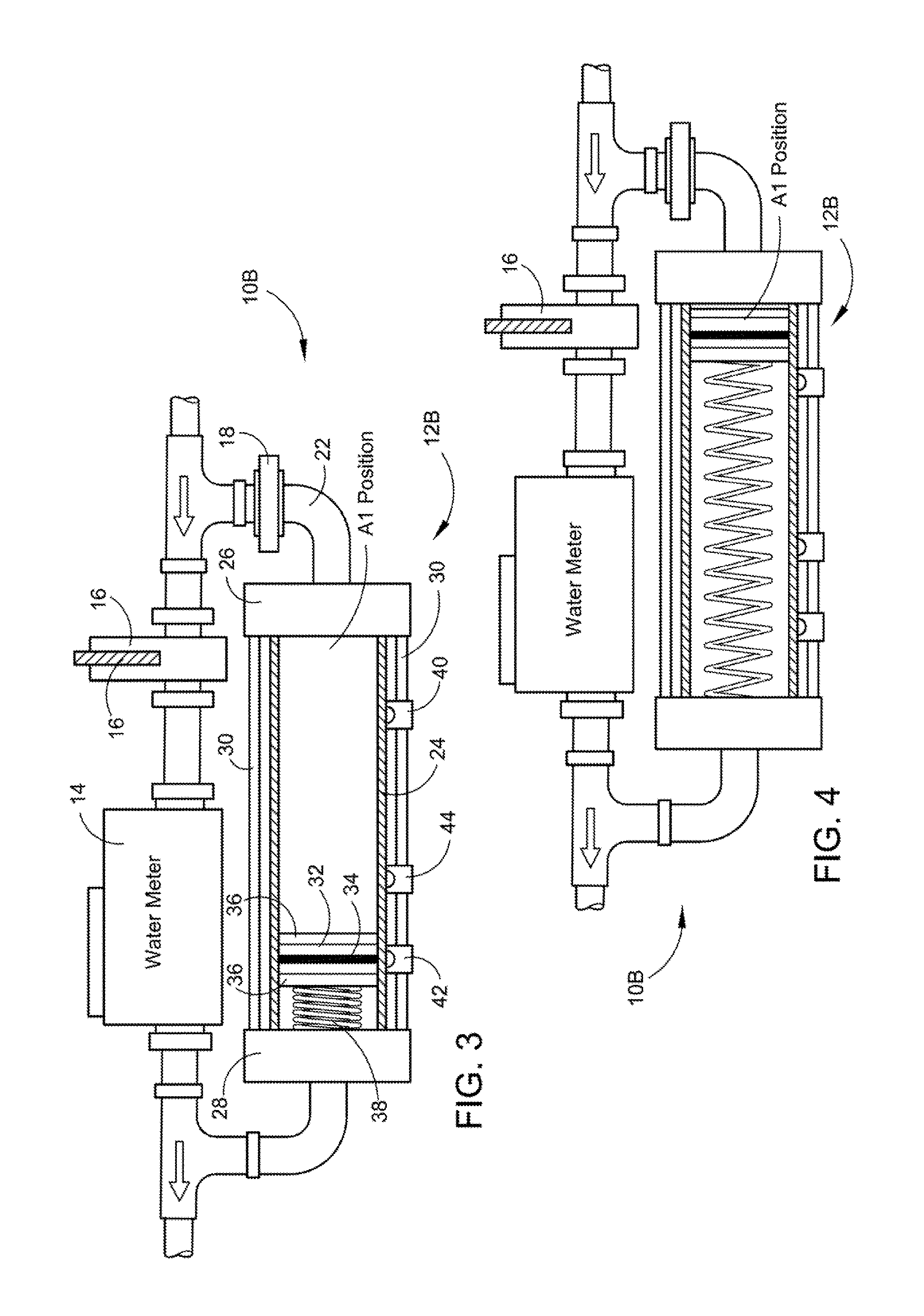
A Positive Displacement Metering Systems (PDMS) using a Water Fill Cylinder (WFC) is provided. It will replace or be paired with an existing conventional water meter. The primary advantage of the PDMS is its ability to detect and measure “micro” flow rates. The PDMS allows the water utility to bill for all water consumed by the customer. The PDMS will only allow 100% detectable flow rates to pass through the water meter attached. Flow rates which are undetectable, or only partially detectable will be accounted for. The PDMS will report the sum of the two meters to the utility. The PDMS will also function as a leak detection device and water conservation tool, will perform automatic or remotely controlled functions like turning off water, when a high flow leak is detected, and report directly to the water utility or tenant of the property being monitored.

Description

FIELD OF THE INVENTION[0001]This application provides a Positive Displacement Metering System (PDMS) using a unique Water Fill Cylinder (WFC) in the preferred embodiment with two or more sensors that will replace the conventional water meter or paired with an existing water meter. In the alternate embodiment with three sensors it will safely indicate any minor or major leakage in the water system in homes and businesses and automatically shut water off if necessary along with notifying the responsible person for the property being monitored.BACKGROUND OF THE INVENTION[0002]The preferred embodiment of the PDMS can play a critical role in how water use is monitored by a utility, and in turn billed to the end user. Since the original water meters inception, there has always been, and continues to be, inaccuracy associated with very low water flow rates.[0003]There are two general types of water meters on the market, mechanical and solid state. These meters are accurate and have served ...

Claims


Application Information

Patent Timeline
IPC IPC(8): G01M3/30E03B7/07G01F7/00
CPCG01M3/30E03B7/072G01F7/00G01F1/05G01F3/04G01F3/16G01F3/18G01F15/0755E03B7/071Y02A20/15
Inventor CRONIN, WILLIAM C.CRONIN, JOHN V.
Owner CRONIN WILLIAM C
Learn More