
Remote control system and method and usage related to such a system

a technology of remote control and control system, applied in the field of remote control system, can solve the problems of increasing complexity of modern vehicle system

Active Publication Date: 2016-12-27
KVASER
View PDF19 Cites 4 Cited by
  • Summary
  • Abstract
  • Description
  • Claims
  • Application Information

AI Technical Summary

Benefits of technology

This solution eliminates the Wrong Model Syndrome, simplifies transmitter design, allows for easy setup and reprogramming of devices, and enables bidirectional communication, reducing the risk of crashes and improving system versatility and efficiency.

Problems solved by technology

It is referred to the facts that modern vehicle systems get more and more complex as the performance of MCUs get more and more powerful.

Method used


Image

  • Remote control system and method and usage related to such a system
  • Remote control system and method and usage related to such a system
  • Remote control system and method and usage related to such a system

Examples


Embodiment Construction

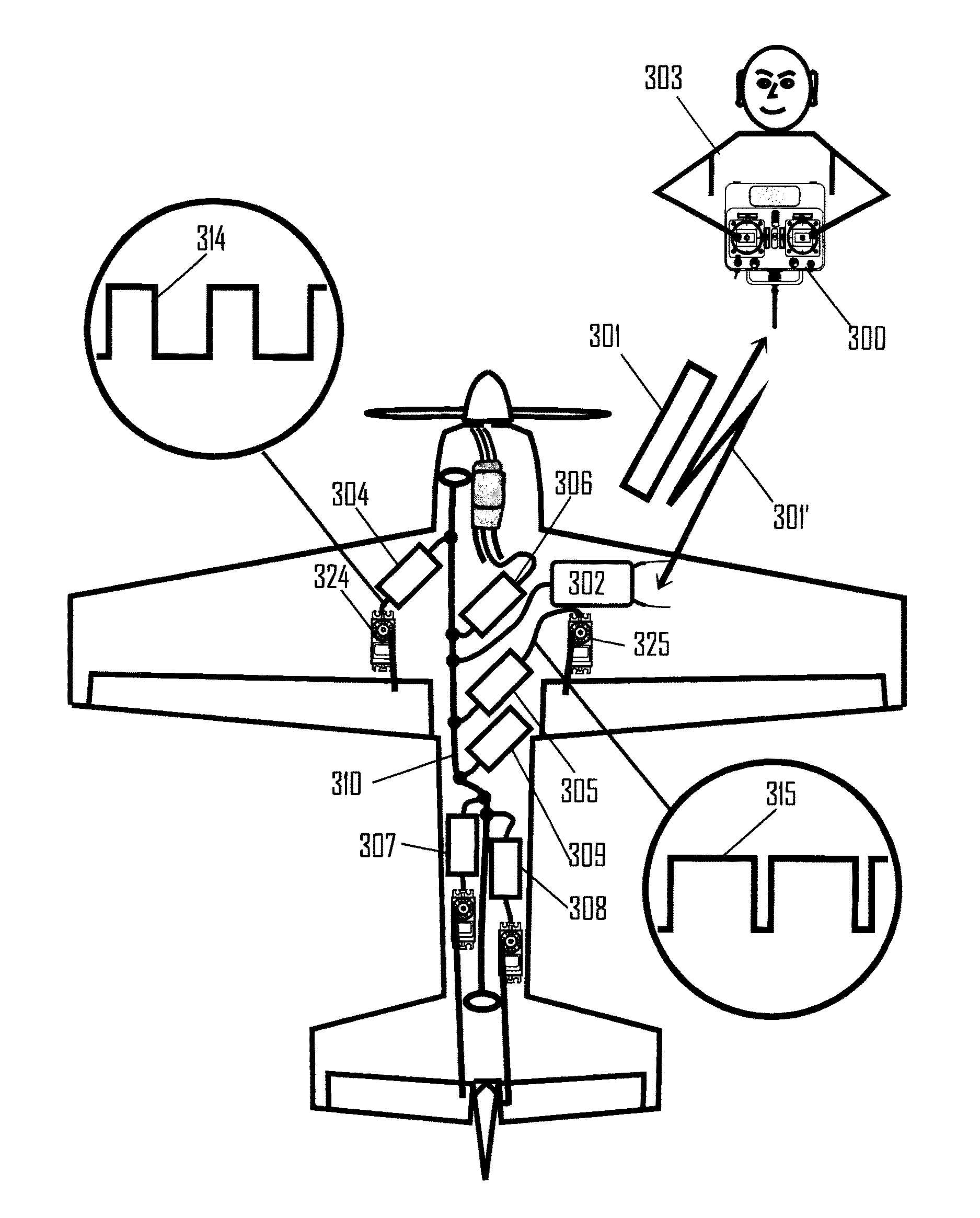
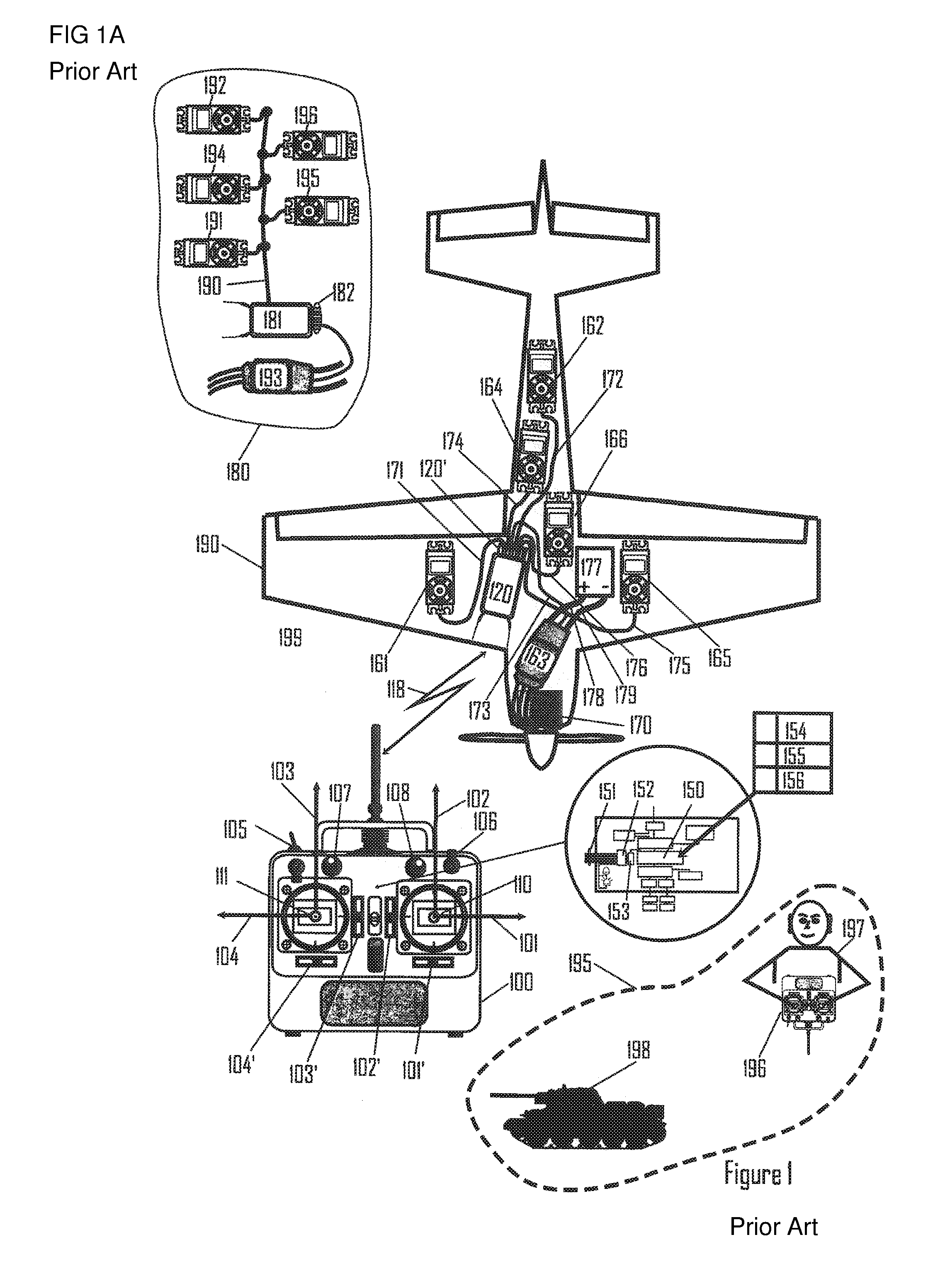
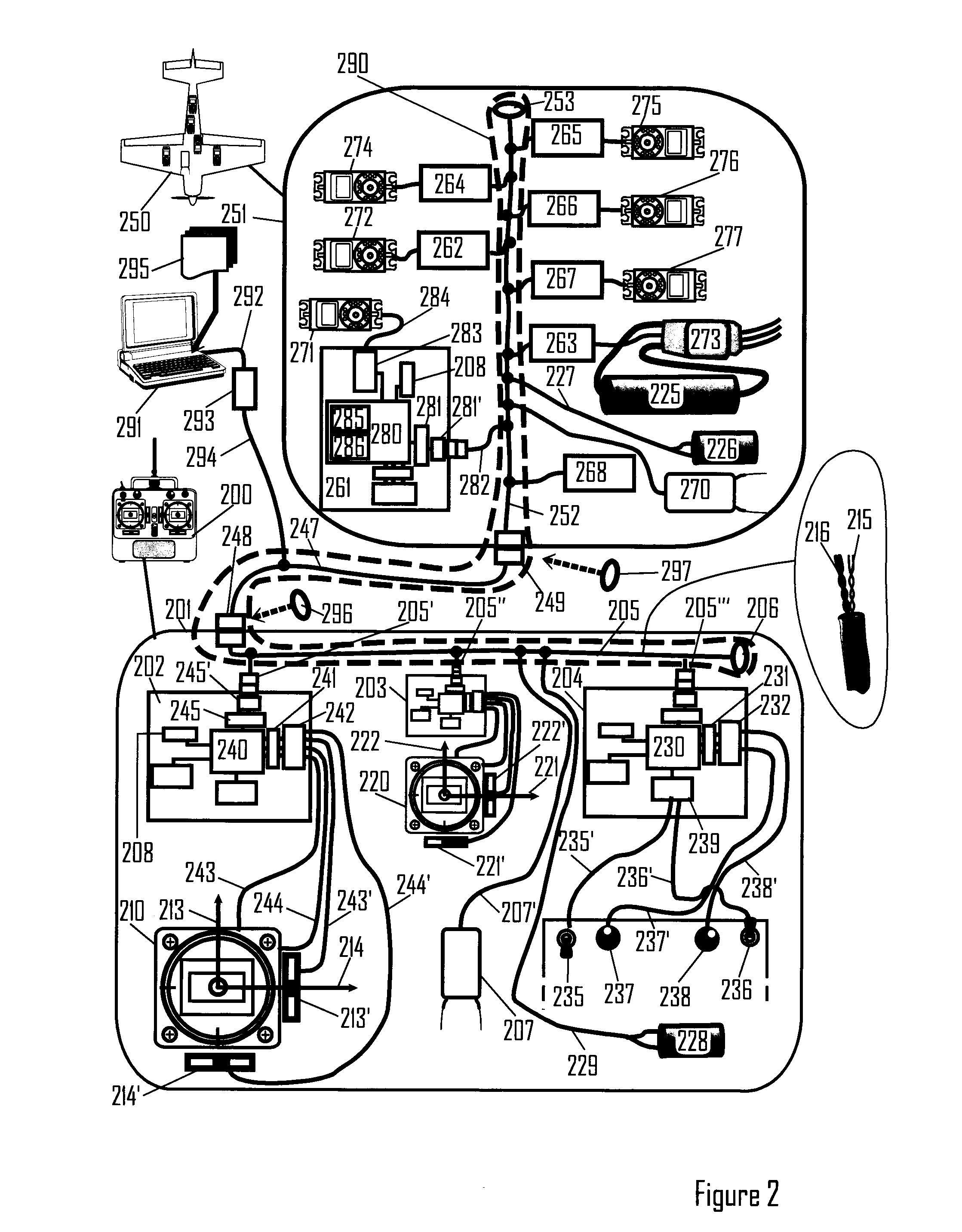
[0061]The state of the art for remotely controlling model vehicle is a centralized system architecture where any and all modifications of control input signals are made in the transmitter and converted to set point values to each actuator in the vehicle to be controlled. The invention proposes a radical change of the current architecture into a distributed embedded control architecture. FIG. 17 shows an overview of the new concept. Only the essentials are shown as an aid to better comprehend the details shown in FIGS. 2 to 16. The problem to be solved is to design and produce a control system to be used for safely and accurately remotely control a number of model vehicles, one at a time. For clarity, the following part of the overview is divided into five sections:[0062]Transmitter[0063]Vehicle[0064]A wired connection between Transmitter and Vehicle[0065]A gateway connection between Transmitter and Vehicle[0066]A wireless connection between Transmitter and Vehicle[0067]Transmitter a...


PUM


Abstract

The invention relates to a remote control system (195) comprising mobile units (190, 1102, 1105), and a by control means (106, 110) provided controller unit for these. Said units are equipped with a function performing means (161) and transferring means (207, 270) that generates information signals (301) respectively transmits the same. Signal processing means (261, 268) and their exerting function (314) for controlling the functions of the respective mobile unit are placed respectively takes place only in the current mobile device. In accordance with the proposed use in connection with the present invention object, a controller area network type of system is constructed with a distributed and integrated network structure (1751). Only signal processing means (1753) and their function exertion means (1754) for controlling of a mobile unit, which is positioned in the actual unit, is used for its control. According to the method establishes a structure of a controller area network type with modular units (1753′), nodes (1753) and a communication protocol (501) for the node communication. All messages transmitted by the nodes are received by the modular units (1754, 1792). A information comparison (1755, 176) is used to select respective message or part thereof.

Description

CROSS-REFERENCE TO RELATED APPLICATIONS[0001]This application is the National Stage of International Application No. PCT / SE2013 / 000169, filed Nov. 1, 2013, which claims priority to Swedish Patent Application No. 1200677-1 filed Nov. 6, 2012.FIELD OF INVENTION[0002]The present invention generally relates i.e. to a remote control system, for example to a radio controlled (RC) system. The invention also relates to a method related to such a system. Said method is i.e. related to a method for controlling radio controlled devices and use of such a system. The invention also relates to a usage of the remote control system.STATE OF THE ART[0003]Most model control systems are characterized in two main parts, one transmitter of control signals and one receiver of control signals. The receiver is connected to a number of actuators, called “servos,” feeding each of them with PWM signals representing setpoint values for positions of the respective actuator. If the model has an electrical motor,...

Claims


Application Information

Patent Timeline
Patent Type & Authority Patents(United States)
IPC IPC(8): A63H30/04H04L12/40B64C39/00G05D1/00B64C39/02
CPCG05D1/0016A63H30/04B64C39/024B64C2201/146B64C2203/00B64U10/25B64U2201/20
Inventor FREDRIKSSON, LARS-BERNO
Owner KVASER
Learn More