
Device and method for producing fiber preforms

a technology of preforms and fibers, applied in the field of fiber preforms, can solve the problems of reducing the dimensional stability of the fixed structure, and avoiding the calculation of placement paths, etc., and achieve the effect of fixed dimensional stability

Active Publication Date: 2017-01-10
VOITH PATENT GMBH
View PDF19 Cites 1 Cited by
  • Summary
  • Abstract
  • Description
  • Claims
  • Application Information

AI Technical Summary

Benefits of technology

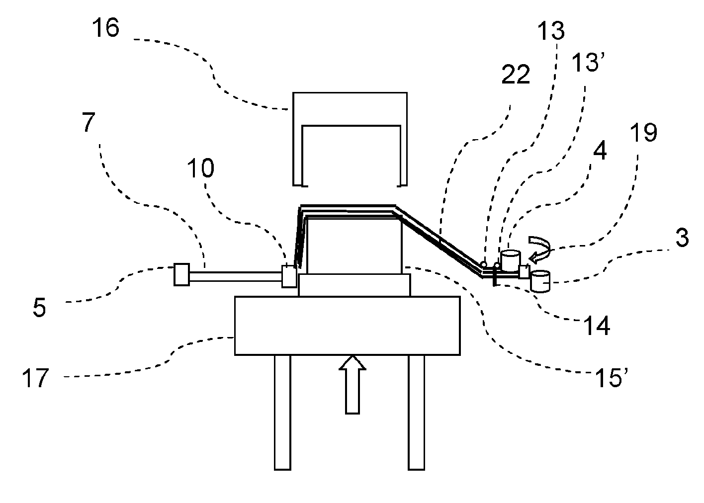
[0014]When the molding tool moves into the tensioned thread or roving layer, the threads are deflected by the molding tool, thus the thread tension would change without being controlled. By providing a control, the thread tension can be controlled during the production process and, in particular, also during draping. This is important since the threads or rovings must not be overburdened, but on the other hand should also not be positioned too loosely in order to obtain optimum component rigidity. In contrast, when using flat semi-finished products the fibers can only be applied largely without tension. And, in placement with a fiber placement head, the thread must be deposited according to the three-dimensionality of the shape with precisely calculated excess length in the embodiment of loops or such, so that the threads then have the tensioned length during draping, that is when the molding tools are brought in or together. By controlling the thread tensions, the normally necessary calculation of the placement paths which is complicated and time consuming can be foregone. The production process becomes thereby simpler and faster, can occur parallelized, and can moreover be adapted flexibly to various component shapes. Especially in batch production of strongly three-dimensional fiber preforms the advantages pay off. The thread tensioning control is important even if a plurality of grippers, during tensioning of the threads or rovings, are located in different intermediate positions, for example near or along one outer contour of a molding tool. The result later on is only a very small amount of scrap of expensive fibrous material. However, the severe deflections of the threads or rovings occurring due to this can only be controlled by controlling the thread tensions. In connection with simple, for example linear paths for the grippers, simple thread guidance with low friction is also achieved. Thus, a plurality of threads or rovings can simultaneously be tensioned quickly and controlled adjacent to each other. The device is thereby configured such that it is capable of placing threads or roving material at rates of more than 2 kilograms per minute (kg / min) or even more than 3 kg / min. Moreover, the unwind stations, as well as the thread guides, can remain stationary due to the grippers.
[0041]It can also be advantageous that the respective gripper is displaced such that the thread tensions adjust. This may be done alternatively or in addition to the adjustment of the thread tensions via releasing of threads or rovings.

Problems solved by technology

In contrast, when using flat semi-finished products the fibers can only be applied largely without tension.
By controlling the thread tensions, the normally necessary calculation of the placement paths which is complicated and time consuming can be foregone.
The result later on is only a very small amount of scrap of expensive fibrous material.
However, the severe deflections of the threads or rovings occurring due to this can only be controlled by controlling the thread tensions.
The flat semi-finished products are quite expensive because of prefabrication.
With strongly three-dimensional components there is the additional risk of wrinkling when using large area semi-finished products.
In small area components on the other hand, the expenditure for cutting and joining of the individual components increases.

Method used


Image

  • Device and method for producing fiber preforms
  • Device and method for producing fiber preforms
  • Device and method for producing fiber preforms

Examples


Embodiment Construction

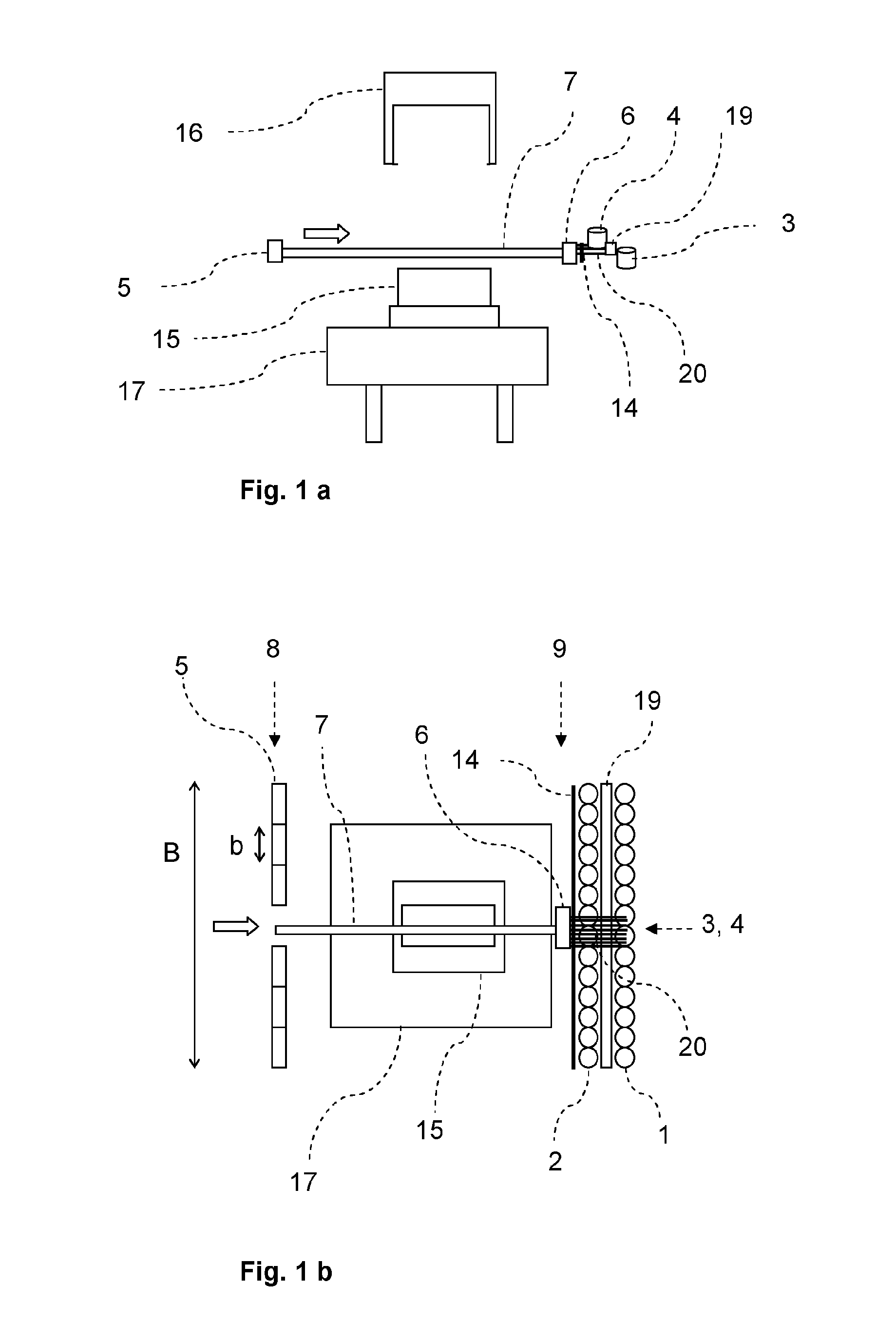
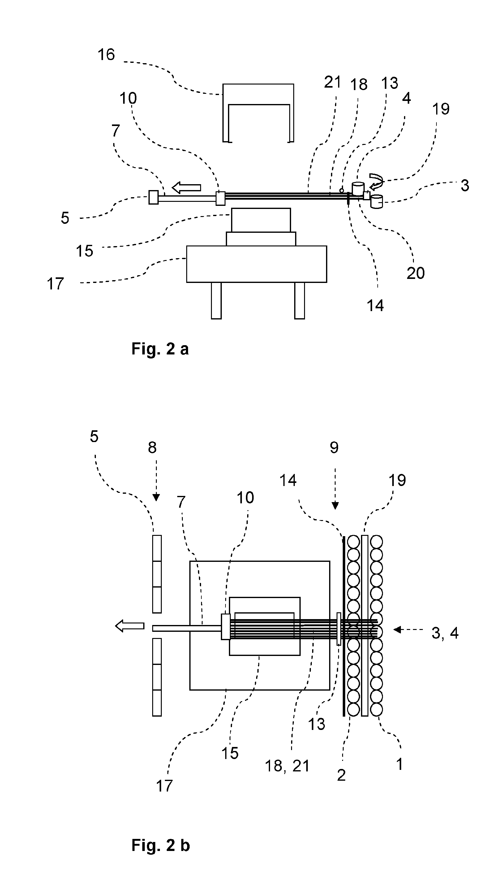
[0065]Referring now to the drawings, and more particularly to FIGS. 1a-7b, there is shown an embodiment of the present inventive device in various process steps. The inventive device is capable of carrying out the following process steps sequentially or partially parallel to one another:[0066]provision of threads or rovings and possibly the binder material;[0067]gripping the required threads or rovings and possibly the binder material;[0068]tensioning of the required threads or rovings by positioning the grippers accordingly;[0069]first draping over a first molding tool;[0070]second draping with a second molding tool;[0071]fixing the layer of threads or rovings;[0072]severing of threads or rovings on both sides of the molding tools;[0073]rewinding the released and unused threads or rovings;[0074]opening the molding tooling tools; and[0075]rotating and / or passing forward a molding tool with the applied layer.

[0076]Repeat of the sequence is feasible for placement of additional layers ...


PUM

PropertyMeasurementUnit
widthaaaaaaaaaa
widthaaaaaaaaaa
widthaaaaaaaaaa

Abstract

A device for producing fiber preforms includes a plurality of unwind stations, a plurality of grippers and at least one first molding tool. Each gripper is movable on a path between a maximum position and a pick-up position. The pick-up position is provided at a thread transfer point and is closer to the unwind station than the maximum position. The first molding tool has a draping position in the region of the connecting lines between the maximum position and the thread transfer points, and a starting position outside the connecting lines. A thread tension control for the threads or rovings is provided.

Description

CROSS REFERENCE TO RELATED APPLICATIONS[0001]This is a continuation of PCT application No. PCT / EP2012 / 051293, entitled “DEVICE AND METHOD FOR PRODUCING FIBER PREFORMS, WHICH ARE A PRECURSOR IN THE PRODUCTION OF FIBER-REINFORCED PLASTIC COMPONENTS IN PARTICULAR”, filed Jan. 27, 2012, which is incorporated herein by reference.BACKGROUND OF THE INVENTION[0002]1. Field of the Invention[0003]The present invention relates to a device for producing fiber preforms which, for example, are a precursor in the production of fiber reinforced plastic components. The present invention moreover relates to a method for producing fiber preforms which are, for example, a precursor in the production of fiber reinforced plastic components using a device according to the present invention.[0004]2. Description of the Related Art[0005]Fiber reinforced plastic consists of a matrix material which, among other factors provides the stiffness, and of fibers which are embedded into the matrix material and which,...

Claims


Application Information

Patent Timeline
Patent Type & Authority Patents(United States)
IPC IPC(8): B29C70/02B29C70/38B29B11/16B29C70/56B29C70/54B29C70/20
CPCB29C70/02B29B11/16B29C70/382B29C70/541B29C70/56B29C70/207B29C70/545
Inventor GOTTINGER, MARCOKAISER, MICHAEL
Owner VOITH PATENT GMBH
Learn More