Ball and socket joint for a vehicle

a technology for vehicles and socket joints, applied in the field of ball socket joints for vehicles, can solve the problems of inaccessible direct measurement of force, prone to large disturbing influences of derived parameters, and inability to determine the force in every situation, etc., and achieve the effect of reducing the number of sensors and reducing the number of derived parameters

Active Publication Date: 2017-01-17
ZF FRIEDRICHSHAFEN AG
View PDF23 Cites 9 Cited by
  • Summary
  • Abstract
  • Description
  • Claims
  • Application Information

AI Technical Summary

Benefits of technology

[0006]Starting from there the purpose of the present invention is to provide an inexpensive possibility for determining the axial force.
[0021]In a preferred alternative the ball socket is a one-piece ball socket provided with at least one slot, for example in the area of its pin opening. In particular, the slot extends in the axial direction and is advantageously open to the pin opening. By virtue of the slot the insertion of the joint ball into the one-piece ball socket through the pin opening can be facilitated. If, as described above, a pressure is exerted on the ball socket in order to increase the frictional torque, then the slots in the axial direction give the advantage that space is made available for the elastic deformation of the ball socket.
[0026]According to one design, at its outer area facing toward the pressure element the ball socket is of conical shape. Preferably, the pressure element has a conical recess into which the conical outer area of the ball socket facing toward the pressure element fits. In a further development, at its outer area facing toward the abutment of the housing the ball socket is of conical shape. Preferably, the housing abutment has a conical recess into which the conical outer area of the ball socket facing toward the housing abutment fits. This conical design makes for particularly effective force transfer to the ball socket.
[0029]The joint housing preferably comprises an opening opposite the pin opening. Through this opening all the above-mentioned components, beginning with the ball pin and ball socket, can be inserted into the housing. The housing is then closed by suitable closure means. Suitable for that purpose are a cover or closing rings rolled together with the end of the housing. Alternatively, the housing can have at its end a thread so that the housing can be closed with a housing cover having a corresponding matching thread. The version with a thread thus enables the joint housing to be opened non-destructively in order to maintain or replace the ball joint or individual components thereof.

Problems solved by technology

However, the frictional torque cannot be determined in every situation.
These derived parameters, however, are prone to large disturbing influences due to interfering forces from outside, wear in the ball joint, elastic effects and friction in the system, temperature dependencies and other influences which are difficult to allow for.
Direct measurement of the force requires sensors which, although known from the field of measurement technology, are not accessible in the case of large production runs (such as in the automobile industry) for cost reasons.

Method used


Image

  • Ball and socket joint for a vehicle
  • Ball and socket joint for a vehicle
  • Ball and socket joint for a vehicle

Examples


Embodiment Construction

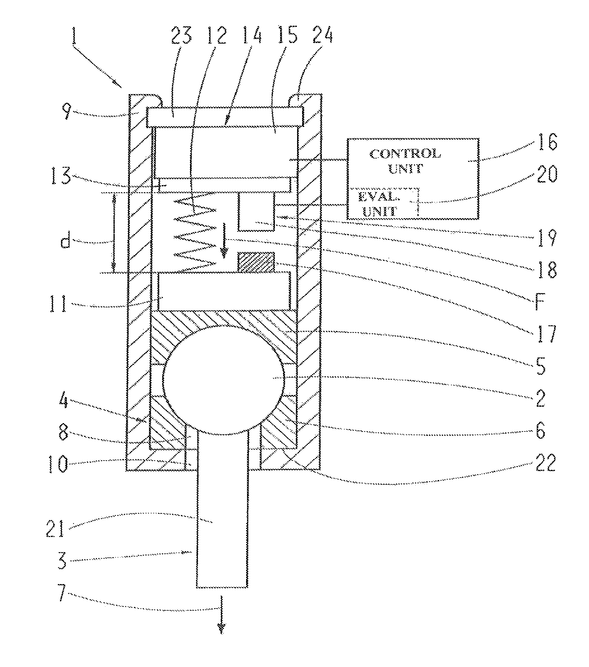
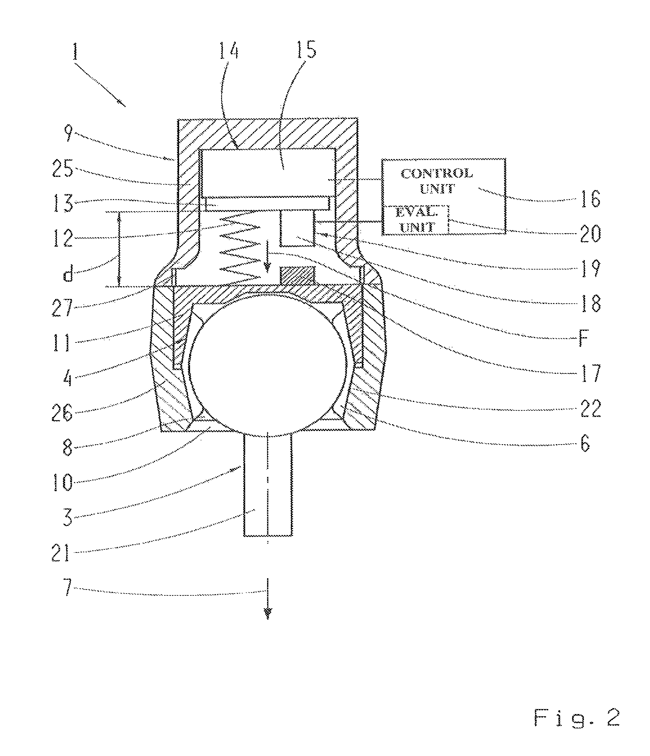
[0033]FIG. 1 shows a schematic longitudinal section through a first embodiment of a ball joint 1, wherein a ball pin 3 is fitted with its joint ball 2 able to rotate and / or swivel within a ball socket 4. The ball socket 4 comprises a first ball socket component 5 and a second ball socket component 6, the ball socket components 5 and 6 being in contact on different sides in an axial direction 7 with the joint ball 2. Furthermore, the second ball socket component 6 has a pin opening 8 through which the ball pin 3 extends axially out of the ball socket 4. In this first embodiment the ball socket 4 is made in two parts so that the ball socket components 5 and 6 are separate components. The ball socket 4 is arranged together with the joint ball 2 in a joint housing 9, which is also provided with a pin opening 10 through which the ball pin 3 extends out of the housing 9. The ball pin 3 has a pin portion 21 connected solidly to the joint ball 2.

[0034]The first ball socket component 5 can b...


PUM

PropertyMeasurementUnit
pressureaaaaaaaaaa
axial lengthaaaaaaaaaa
forceaaaaaaaaaa

Abstract

A ball joint for a vehicle, with a ball pin that has a joint ball, a joint housing that encloses the joint ball and is provided with a pin opening, in which the joint ball of the ball pin is fitted and able to move. The ball pin extends out of the joint housing through the pin opening. An actuator can press a pressure element, in an axial direction, against the joint housing in such a manner that pressure can be exerted by the joint housing and the pressure element onto the joint ball. The actuator acts upon a spring which acts upon the pressure element. The length of the spring can be measured by a displacement sensor.

Description

[0001]This application is a National Stage completion of PCT / EP2013 / 055594 filed Mar. 19, 2013, which claims priority from German patent application serial no. 10 2012 206 537.7 filed Apr. 20, 2012.FIELD OF THE INVENTION[0002]The invention concerns a ball joint for a vehicle, with a ball pin comprising a joint ball, a joint housing that encloses the joint ball and that is provided with a pin opening, in which housing the joint ball of the ball pin is fitted so that it can move, wherein the ball pin projects out of the joint housing through the pin opening, and an actuator which biases a pressure element in an axial direction onto the joint housing so that by virtue of the joint housing and the pressure element a pressure can be exerted on the joint ball.BACKGROUND OF THE INVENTION[0003]DE 102 45 983 A1 describes a ball joint with a housing, two bearing socket elements arranged in the housing, a joint body comprising a pin and a joint ball which fits between the two bearing socket el...

Claims


Application Information

Patent Timeline
Patent Type & Authority Patents(United States)
IPC IPC(8): B60G7/00F16C11/10F16C11/06G01L1/04G01L5/00
CPCB60G7/005B60G7/006F16C11/0647F16C11/106G01L1/04G01L5/0023B60G2202/40B60G2204/14B60G2204/416Y10T403/20F16C2326/05F16C25/02F16C2233/00
Inventor GRANNEMANN, BERNDRECHTIEN, MARTIN
Owner ZF FRIEDRICHSHAFEN AG
Why Eureka
Try Eureka