Detection of radar objects using a radar sensor of a motor vehicle

a technology of radar sensor and motor vehicle, which is applied in the direction of reradiation, measurement devices, instruments, etc., can solve the problems of computing effort during measurement analysis, inability to clearly determine the relative velocity and distance from the baseband signal assigned to the frequency modulation ramp, etc., and achieve the precise velocity and distance estimation of detected radar objects and good separability of simultaneously detected radar objects

Active Publication Date: 2017-01-17
ROBERT BOSCH GMBH
View PDF11 Cites 3 Cited by
  • Summary
  • Abstract
  • Description
  • Claims
  • Application Information

AI Technical Summary

Benefits of technology

[0013]The object of the present invention is to provide a novel method for detecting radar objects with the aid of a radar sensor of a motor vehicle, which allows precise velocity and distance estimation of detected radar objects and good separability of simultaneously detected radar objects with the least possible hardware outlay and computing effort.
[0022]In particular, the first information is ascertained based on a frequency position of the radar object in the frequency spectrum of the at least one partial signal. The frequency modulations are preferably in ramps, since this simplifies the analysis. By ascertaining a relationship between the relative velocity and the distance of a radar object from a partial signal of the measuring signal, which is associated with respect to time with a frequency modulation ramp of the transmitted signal, good precision may be achieved without excess demands on the steepness of the frequency ramp. The analysis of the time curve via the sequence of the frequency modulation ramps allows matching with additional information, which may have high precision, in particular with respect to the relative velocity.
[0023]The matching of the first information with the second information preferably takes place under consideration of an ambiguity of the second information, which is determined by an unambiguous range for the relative velocity and optionally the distance. Because such ambiguities are permitted and taken into consideration, the number of the required partial signals and therefore the computing effort for the analysis may be limited, since the relationship, which is encompassed by the first information, between the parameters of the relative velocity and the distance of a radar object is restricted in the case of the matching by the ambiguous second information to certain parameter ranges or parameter points. Therefore, good precision may be achieved without excessive demands on the steepness of the frequency ramps and without excess computing effort, so that the hardware outlay may be limited.
[0024]The method preferably also includes the following step: ascertaining further first information about the relative velocity and the distance of the radar object, based on a frequency spectrum of at least one further one of the partial signals, the further first information including a relationship between a relative velocity and a distance of the radar object, which assigns different relative velocities to different distances, and the at least one partial signal and the at least one further partial signal being assigned to different frequency modulations of the transmitted signal. The ascertainment of the relative velocity and the distance of the radar object is then based on matching of the first information with the second information and with the further first information. In this way, different relationships between the relative velocity and the distance of the radar object may be obtained from the first information and the further first information, the relationships corresponding to straight lines having different slopes in the ν-d space, for example. The consideration of the second information simplifies the matching of the first information with the further first information.

Problems solved by technology

In the case of an FMCW radar sensor, each radar object in the frequency spectrum of a channel emerges in the form of a peak, whose location is a function of the Doppler shift and the runtime of the radar signals, so that unambiguous determination of the relative velocity and the distance is not yet possible from the baseband signal assigned to a frequency modulation ramp.
In order to achieve precision of the determination of the relative velocity and the distance in the chirp sequence method, a high number of steep signal pulses and therefore a great computing effort during the analysis of the measurements are necessary.

Method used


Image

  • Detection of radar objects using a radar sensor of a motor vehicle
  • Detection of radar objects using a radar sensor of a motor vehicle
  • Detection of radar objects using a radar sensor of a motor vehicle

Examples


Embodiment Construction

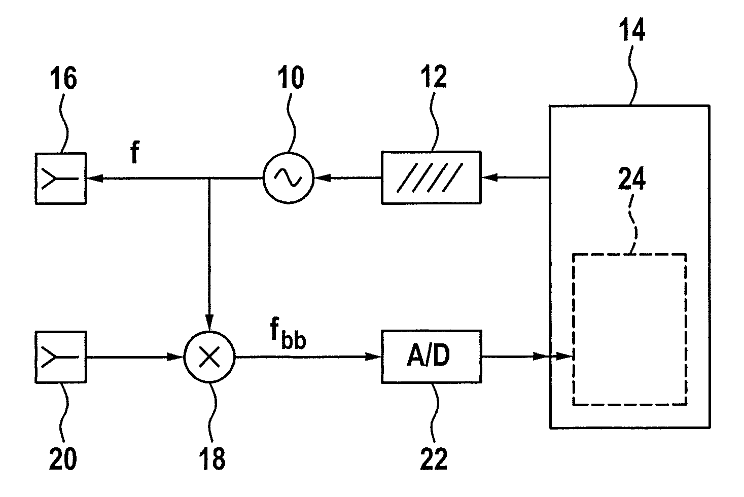
[0041]FIG. 1 schematically shows the construction of a radar sensor system for motor vehicles. The system includes a voltage-controlled high-frequency (HF) oscillator 10 for generating a transmitted signal. Frequency f of HF oscillator 10 is controlled by a frequency modulation device 12, which is in turn controlled by a control and analysis unit 14. One output of HF oscillator 10 is connected to at least one transmitting antenna element 16, in order to emit a transmitted signal of the radar sensor system.

[0042]Furthermore, one output of HF oscillator 10 is connected to a mixer 18. This mixer is configured for the purpose of mixing a received signal received from receiving antenna element 20 with the transmitted signal, to generate a measuring signal in the form of a baseband signal. The baseband signal is digitized by an analog digital converter 22 and supplied to control and analysis unit 14. The mixing and digitization take place while maintaining the phase relationships between ...


PUM


Abstract

In a method for detecting radar objects with the aid of a radar sensor of a motor vehicle, a transmitted signal has a sequence of frequency modulations, to each of which a partial signal of a measuring signal is assigned; first information about the relative velocity and the distance of a radar object is ascertained based on a frequency spectrum of at least one of the partial signals; second information about the relative velocity and the distance of the radar object is ascertained based on a frequency spectrum of a time curve of values of frequency spectra of the partial signals at a frequency position of the radar object in these frequency spectra; and the relative velocity and the distance of the radar object are ascertained based on matching of the first information with the second information.

Description

BACKGROUND OF THE INVENTION[0001]1. Field of the Invention[0002]The present invention relates to a method for detecting radar objects with the aid of a radar sensor of a motor vehicle, in which a measuring signal is generated by mixing a transmitted signal with a received signal, the transmitted signal having a sequence of frequency modulations.[0003]2. Description of the Related Art[0004]Radar sensors are used in driver assistance systems for motor vehicles, for example, in ACC (adaptive cruise control) systems or safety systems, for example, collision warning systems, and are used for the purpose of determining the positions and relative velocities of objects, so that a driving situation may be recognized. For example, in the case of an ACC system within the scope of adaptive cruise control, the velocity of one's own vehicle may be adapted to the velocity of a preceding vehicle and the distance to the preceding vehicle may be regulated to a suitable value. For example, a safety sy...

Claims


Application Information

Patent Timeline
Patent Type & Authority Patents(United States)
IPC IPC(8): G01S13/58G01S7/35G01S13/931
CPCG01S13/584G01S2007/356G01S7/356G01S13/343G01S13/931
Inventor KUEHNLE, GOETZSCHOOR, MICHAEL
Owner ROBERT BOSCH GMBH
Why Eureka
Try Eureka