Chuck tool and bits

a chuck and tool technology, applied in the direction of metal-working holders, positioning apparatus, supports, etc., can solve the problems of reducing the service life of the chuck, and reducing the time consumption of the chuck. the effect of reducing the run-ou

Active Publication Date: 2017-01-24
KEIGHTLEY KYM JOHN
View PDF18 Cites 9 Cited by
  • Summary
  • Abstract
  • Description
  • Claims
  • Application Information

AI Technical Summary

Benefits of technology

[0014]In a further aspect of the invention there is a chuck for use with a drill bit as described herein in, the chuck including: a body; a drill bit centering arrangement for accommodating the constant diameter centering shaft portion of the drill bit, wherein the drill bit is aligned with the axis of rotation of the chuck to reduce run-out; and a drill bit retention arrangement adapted to engage with the lock portion of the drill bit preventing relative longitudinal movement between the drill bit and the body of the chuck. And a drill bit engagement portion of the chuck for engaging the drive shoulder portion of a drill bit to impart rotational forces to the drill bit.

Problems solved by technology

A problem when using chucks to clamp a drill bit is slip.
This occurs during the drilling process as the chuck jaws tend to slip around the shank causing damage.
This results in both salient and recessed radial grooves on the shank which can cause operational problems including out of true rotation and weakening of the shank.
Chucks can also over tighten and jam closed making release of the chuck and drill bit removal difficult continually operating a chuck is also time consuming with drill bit changeovers.
Although useful in connecting drill bits without having to operate a three jaw chuck each time, the arrangement is prone to run-out.
This is seen by the user as rotational wobble from side to side when looking along the length of the drill bit this wobble makes it difficult for a user to drill a hole accurately when drilling into various materials, in particular metals.
Drill bit starts are also very difficult into for example sheet metal.
One of the main reasons for this run-out is that hexagonal shafts and bores are generally mass produced and the accuracy in regard to straightness along their length as well as dimensional accuracy is difficult to maintain compared to round bores and shafts.
This lack of straightness of the bore and shaft as well as play between the bore and shaft when fitted together, result in levels of run-out that, whilst acceptable for some tools, is an unacceptable level of run-out for drills, as any run-out of the mandrel is amplified across the longer length of a drill resulting in large run-out at the drill cutting face.
A further problem is that hex chucks accept only one size shank.
Larger diameter drills require heavier rotational forces and support making the [¼]″ shaft inadequate.
One could have two chucks to adapt to two different shank sizes, one chuck for smaller diameter drills and another chuck for larger diameter drills but this would require changeover of chucks which is cumbersome.

Method used


Image

  • Chuck tool and bits
  • Chuck tool and bits
  • Chuck tool and bits

Examples


Embodiment Construction

[0049]The following detailed description of the invention refers to the accompanying drawings. Although the description includes exemplary embodiments, other embodiments are possible, and changes may be made to the embodiments described without departing from the spirit and scope of the invention.

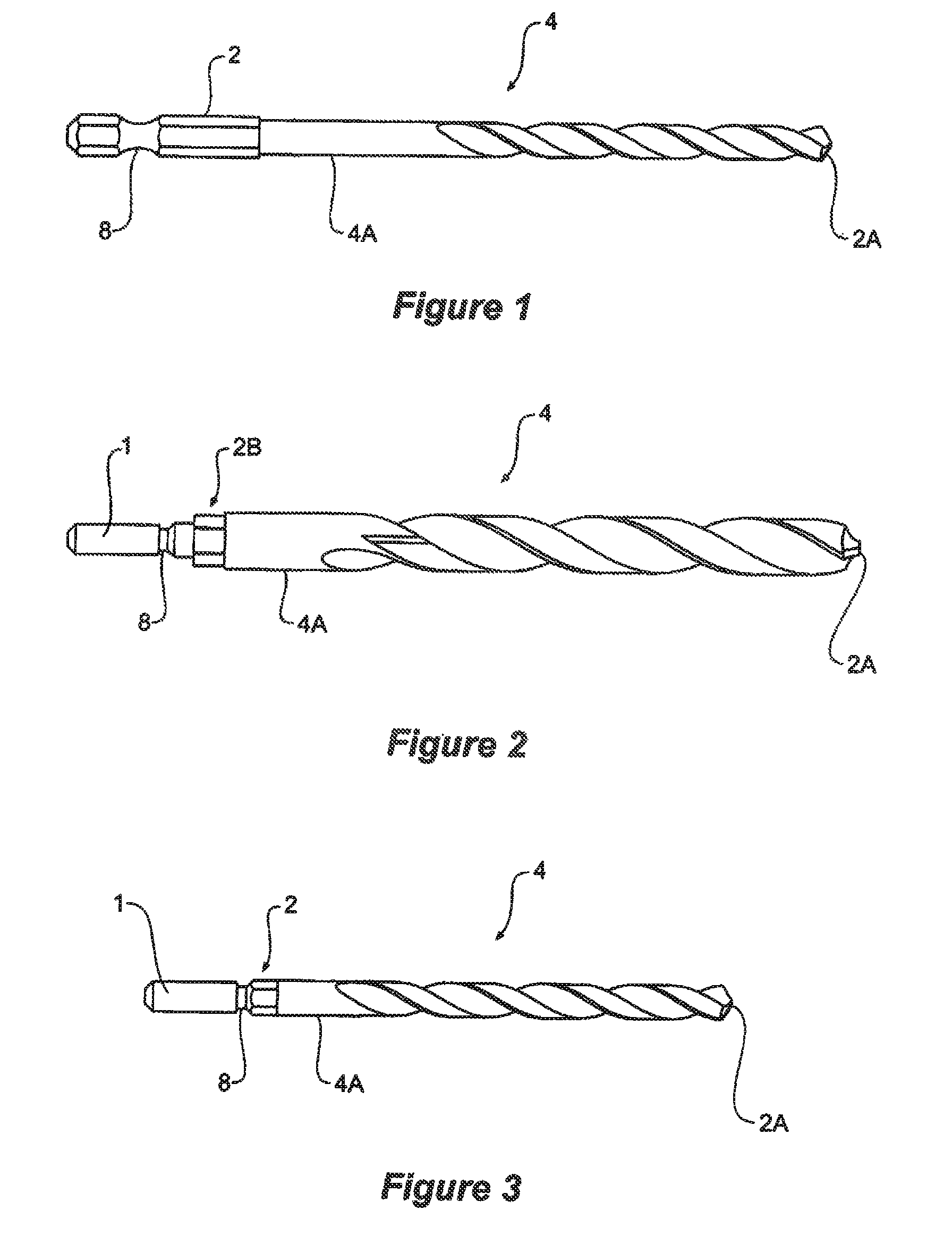
[0050]FIG. 1 shows a commonly available prior art quick change drill bit having an approximately ¼″ hexagonal shank 8 and a locking groove 2 extending around the shank 4A. A cutting face 2A is at the opposite end. The hexagonal shank 8 acts as a drive shoulder to allow rotational engagement of the drill bit by the chuck. Typically a ball detent will act on the groove 8 to prevent the bit pulling out during use.

[0051]A problem with this arrangement is the hex drive means is also the centering means which cannot be turned to be formed during manufacture. Each flat must be machined, ground or formed by forging resulting in run-out problems as discussed earlier in the specification.

[0052]FIG. 3...


PUM

PropertyMeasurementUnit
diametersaaaaaaaaaa
diametersaaaaaaaaaa
diameteraaaaaaaaaa

Abstract

A tool arrangement and chuck apparatus for quick change of a range of tools; particularly, a quick change chuck adapted to engage various diameter drill bits, tools and tool holders. The tools are rotatable in a chuck or adaptor and have at one end a centering shaft portion having a constant diameter for multiple tool end diameters and shapes, a drive shoulder portion and a lock portion. The chucks have a tool centering arrangement for accommodating the constant diameter centering shaft. The chucks are also described as having tool bit release mechanism operable to disengage the tool from a retention mechanism when a force is applied inwards of the body of the chuck by the user to allow the tool bit to be removed longitudinally from the chuck but also arrange to allow the tool bit to be inserted longitudinally into the chuck without requiring any other user operation.

Description

FIELD OF THE INVENTION[0001]The present invention relates to a tool arrangement and chuck apparatus for quick change of a range of tools. In particular, a quick change chuck adapted to engage various diameter drill bits, tools and tool holders.REFERENCE[0002]Incorporated by reference into this specification is Australian provisional patent application 2011901515 dated 21 Apr. 2011 entitled Chuck Tool and Bits Arrangement having the same inventor as the subject application.BACKGROUND OF THE INVENTION[0003]Chucks used to rotationally support tools are commonly known. Chucks are usually attached to a power drill and are generally of the 3 jaw type which are adjustable to allow clamping of different diameter tool shanks. Drill bits are most commonly clamped in a chuck and are typically long and cylindrically shaped, having a round shank at one end for mounting in a chuck and at the opposite end a cutting face. Drill bits vary in diameter depending on the size hole to be drilled and are ...

Claims


Application Information

Patent Timeline
Patent Type & Authority Patents(United States)
IPC IPC(8): B23B51/12B23B31/107B23B51/00B23B47/00B25B23/00B23Q3/12B23B31/00
CPCB23B51/12B23B31/005B23B31/008B23B31/1071B23B47/00B23B51/00B23Q3/12B25B23/0035B23B2231/0232B23B2231/0256B23B2231/0268B23B2231/04Y10T279/17Y10T279/17196Y10T279/3418Y10T408/907Y10T408/957B23B31/107
Inventor KEIGHTLEY, KYM
Owner KEIGHTLEY KYM JOHN
Why Eureka
Try Eureka