Mineral material feed apparatus, a plant and a method

a technology of mineral material and feed apparatus, which is applied in the direction of mechanical conveyors, gas current separation, solid separation, etc., can solve the problems of difficult adjustment of feed conveyors, inability to achieve the desired distance between feed conveyors and feed hoppers, and inaccuracy of manufacturing, so as to enhance the usability of process and process apparatus operated in process, enhance the usability of process and process apparatus, and facilitate the adjustment of feed devi

Active Publication Date: 2017-01-31
METSO OUTOTEC (FINLAND) OY
View PDF9 Cites 0 Cited by
  • Summary
  • Abstract
  • Description
  • Claims
  • Application Information

AI Technical Summary

Benefits of technology

[0019]Preferably seals are fixed to the wall of the feed box by plates which are pressable towards a rear surface of the wall. Preferably the seals are directed towards the transport surface. Preferably the distance adjustment members are configured to decrease the distance between the transport surface of the feed device and the bottom edge of the wall of the feed box to compensate wear of the seals.
[0029]Following advantages can be achieved by the presented solutions. The adjustability of the distance between the feed device such as the feed conveyor and the feed hopper enhances operation of the feed apparatus.
[0030]Due to the adjustability of the distance between the feed device and the feed hopper, wedging of material in between the transport surface and the wall of the feed hopper can be reduced and so the usability of the process and of the apparatus operated in the process enhances. Due to the easy adjustability of the feed device the gap between the feed hopper and the feed device can easily be formed opening in the material transport direction by which the wedging of the material is reduced. Additionally, leaking of material from the feed hopper can be reduced and avoided.
[0031]Wearing of the seals directed towards the transport surface of the feed device can easily be compensated by adjusting the transport surface of the feed device to the direction of the seals. For example, the wear of the longitudinal seals of the feed conveyor can be easily compensated speedier than before by adjusting the conveyor and / or the seals so that down-time of the process caused by the adjustment is reduced. The adjustment of the longitudinal seals can be made more infrequently because the moving of the feed device towards the seals is easy. The adjustment of the longitudinal seals can in some cases be made easier among others by forming the longitudinal seal unitary instead several seals. The plates pressing the seal can additionally be formed of several short parts wherein the detaching of a seal sticked to the plate becomes easier. The detaching of the seal from the plate and the rear wall of the feed box can be facilitated by the one or several openings formed to the plate and / or by the grip form formed to the seal.

Problems solved by technology

Manufacturing inaccuracies of the feed conveyor and of the structures being the object of the fixing complicate the fixing of the feed conveyor.
The desired distance between the feed conveyor and the feed hopper is not achieved easily.
Mounting inaccuracies caused by the interface between the feed hopper and the feed conveyor complicate the operation of the feeder.
In some cases a gap between a side wall of the feed hopper and a conveyor belt is too large or too small wherein the stones may between the side wall and the conveyor.
If the gap between the side wall and the conveyor belt is too large material leaks through the side wall and the conveyor belt.

Method used


Image

  • Mineral material feed apparatus, a plant and a method
  • Mineral material feed apparatus, a plant and a method
  • Mineral material feed apparatus, a plant and a method

Examples


Embodiment Construction

[0044]In the following description, like numbers denote like elements. It should be appreciated that the illustrated drawings are not entirely in scale, and that the drawings mainly serve the purpose of illustrating some example embodiments of the invention.

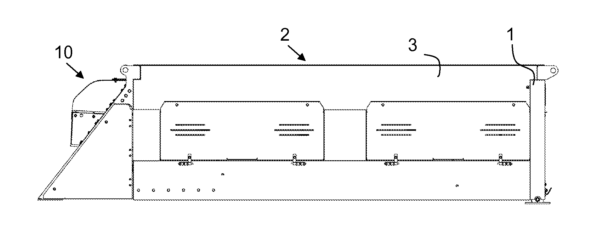
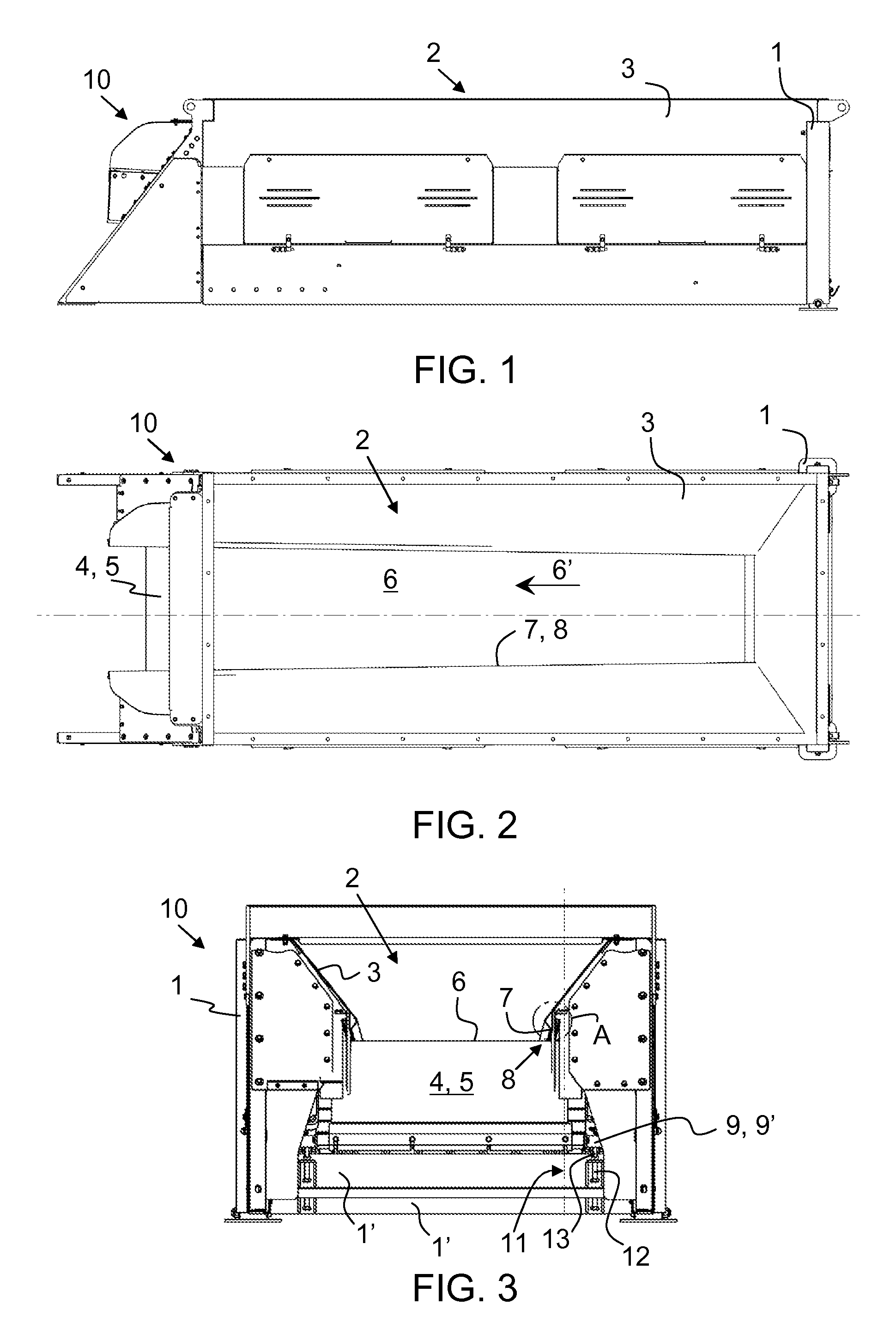
[0045]FIG. 1 shows a side view of a feed apparatus 10 for a mobile mineral material processing plant. The feed apparatus comprises a first frame 1 to which is fixed a feed box 2 of which the term feed hopper is used also in some cases. The feed box has walls 3 for mineral material to be loaded to the feed apparatus and to guide the mineral material onto a feed device 4 below the feed box.

[0046]The invention is not limited to the embodiment of the feed apparatus having stationary walls shown in this description. The solution of the invention relates also to such a feed hopper which has side pivotable walls. A feed hopper equipped with pivotable walls is shown in publication EP1771252B1.

[0047]FIG. 2 shows a top view of the feed app...


PUM


Abstract

A feed apparatus for feeding mineral material includes a first frame, a feed box fixed to the first frame and having walls for the mineral material to be loaded to the apparatus, and a feed device joined to the first frame so that the material ends up onto a transport surface of a transport member of the feed device. The transport surface and a bottom edge of the wall of the feed box form a gap therebetween. The feed apparatus includes distance adjustment members to move the transport surface and the bottom edge relative to each other. Preferably the distance adjustment members are pivoted on the first frame and the feed device. A method for adjusting the feed apparatus includes moving the transport surface of the feed device and the bottom edge of the wall of the feed box relative to each other by distance adjustment members.

Description

CROSS-REFERENCE TO RELATED APPLICATIONS[0001]This application claims priority to PCT / FI2013 / 051159, filed Dec. 12, 2013, and published in English on Jun. 26, 2014 as publication number WO 2014 / 096533, which claims priority to FI Application No. 20126366, filed Dec. 21, 2012, incorporated herein by reference.TECHNICAL FIELD[0002]The invention relates to a feed apparatus and a method for adjusting a mineral material feed apparatus. The invention relates particularly, though not exclusively, to a mineral material feed apparatus in which material, fed into a feed hopper or a corresponding feed box, is moved forwards by a feed device.BACKGROUND ART[0003]Mineral material, for example rock, is gained from the earth for processing by exploding or excavating. The rock can also be natural rock and gravel or construction waste. The processing is typically crushing and / or screening of material. Mobile processing plants and stationary applications are used in the processing. An excavator or whee...

Claims


Application Information

Patent Timeline
Patent Type & Authority Patents(United States)
IPC IPC(8): B65G15/00B65G37/00B02C23/02B07B11/06
CPCB65G37/00B02C23/02B07B11/06
Inventor PORVALI, SAMIYLA-OUTINEN, RIKU
Owner METSO OUTOTEC (FINLAND) OY
Why Eureka
Try Eureka