Cantilevered watercraft canopy

a technology for watercraft and cantilevers, applied in vessel parts, vessel construction, transportation and packaging, etc., can solve the problems of affecting the enjoyment of boating experience, affecting the safety of watercraft, and virtually impossible for people with dexterity disabilities to skip boating altogether, etc., to achieve convenient installation and stricken seasonally.

Active Publication Date: 2017-01-31
DESIGNER DIRECT INC
View PDF59 Cites 16 Cited by
  • Summary
  • Abstract
  • Description
  • Claims
  • Application Information

AI Technical Summary

Benefits of technology

[0011]It is an object of the invention to provide a watercraft canopy that replaces the need to cover watercraft during non-use.
[0013]It is an object of the invention to provide a watercraft canopy that is easily installed and stricken seasonally.

Problems solved by technology

While seemingly simple, this task can be daunting and can greatly diminish enjoyment of the boating experience.
This task can be time consuming and physically demanding, and, for people with dexterity disabilities, virtually impossible.
Often times, boaters skip boating altogether because of the difficulty associated with manual covers.
U.S. Pat. No. 7,353,769 to Unrast provides a cantilevered liftable canopy, which addresses the need to span the mooring area, but still requires complex mechanical action to use and does not provide access to the watercraft without lifting the canopy.
Depending on the means of providing power, this activity can be difficult, such as during power outages or when the pulley mechanism has malfunctioned, leaving the boater to temporarily revert back to individual covers.
Additionally, this alternative is relatively expensive, both for the initial investment, as well as the ongoing seasonal installation done most often with barges and cranes.
Lastly, the lift stations are a disruption to the natural environment, as while in the water they disturb the lake bed with underwater supports and resting pads, and during the off-season are placed helter-skelter along the shorelines, diminishing the public's use and enjoyment of the waterfront.

Method used


Image

  • Cantilevered watercraft canopy
  • Cantilevered watercraft canopy
  • Cantilevered watercraft canopy

Examples


Embodiment Construction

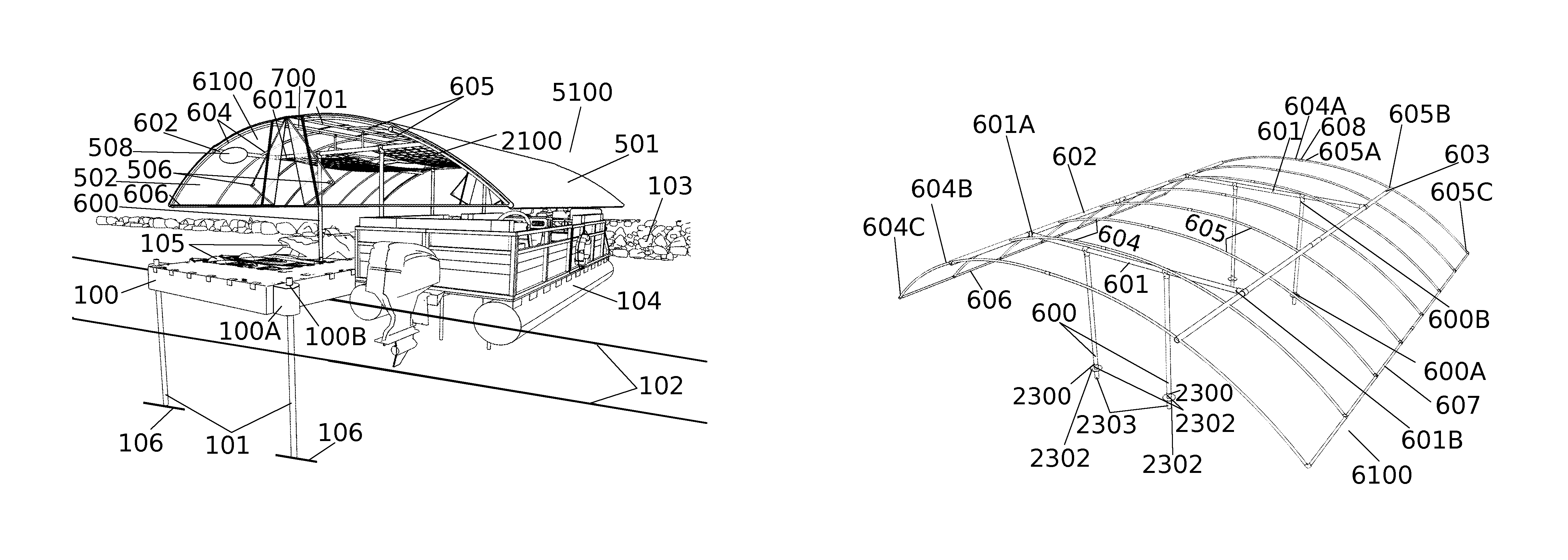
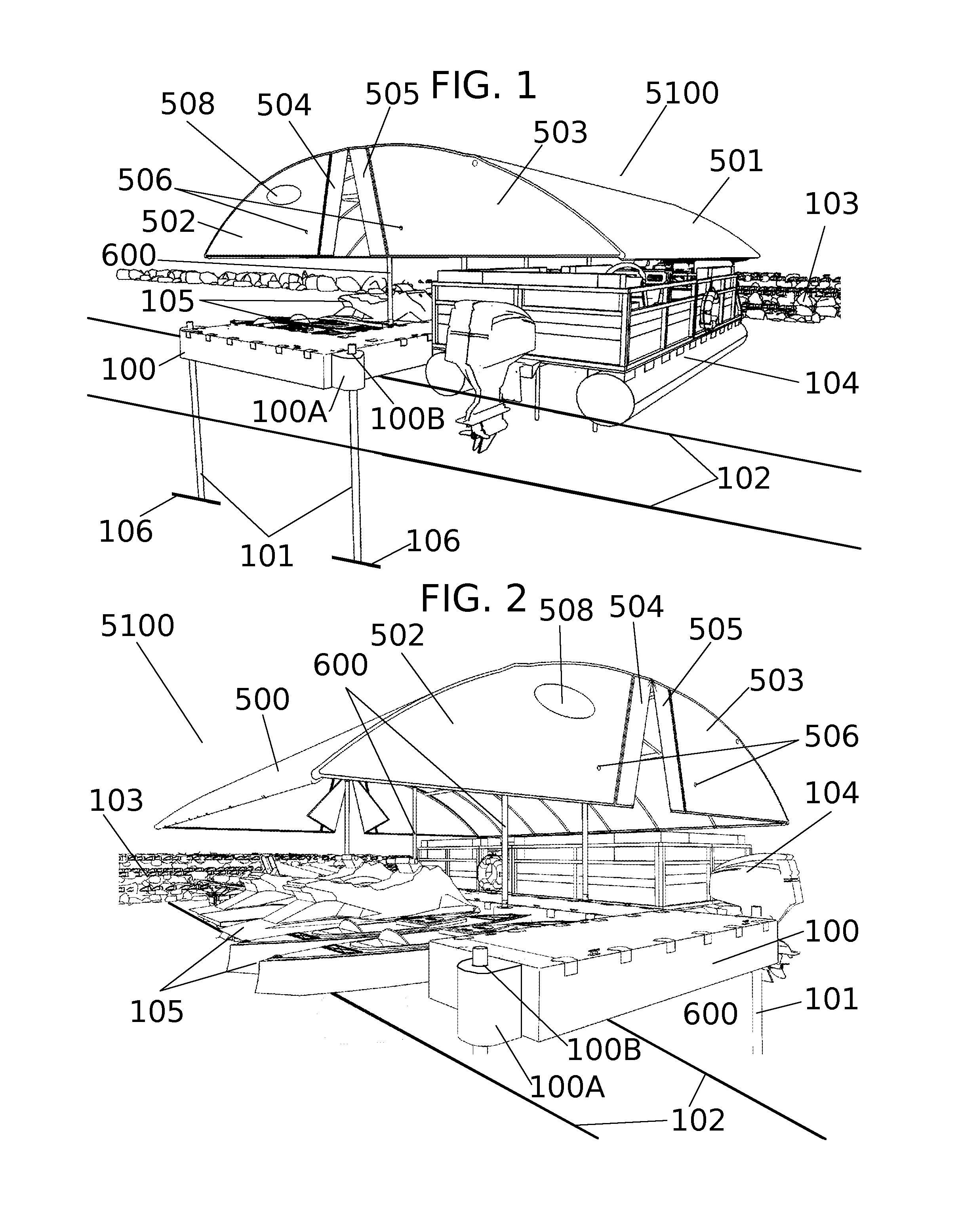
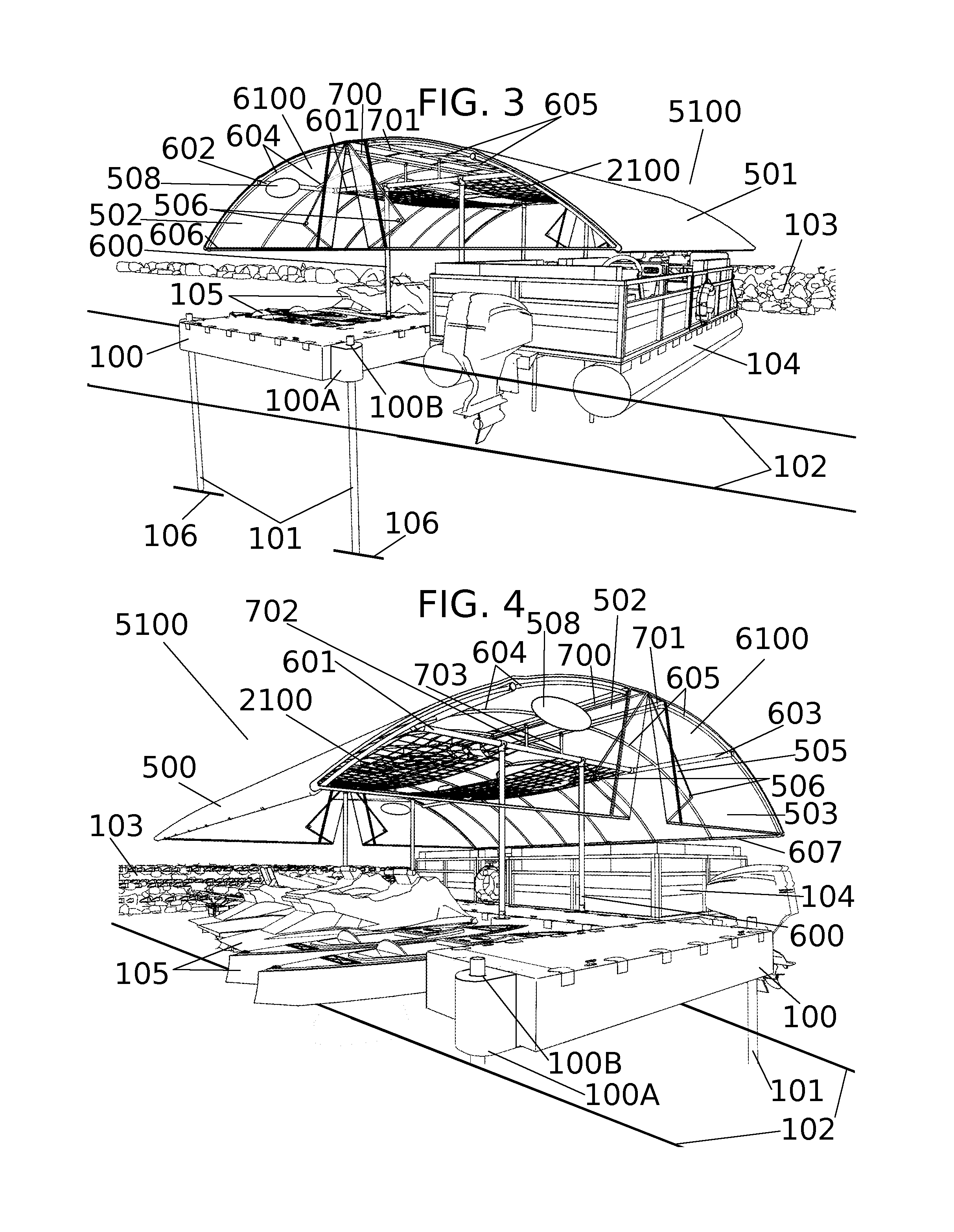
[0060]Referring now to the invention in more detail, the invention is directed to a cantilevered watercraft canopy. As shown in FIGS. 1-4, the environment of the preferred environment is installation on a dock 100 or pier such that mooring areas on both sides of the dock 100 are covered by the canopy. As depicted in FIGS. 1-4, defined within the environment are the water level 102 (the water level 102 is represented by a pair of parallel oblique lines, which define a plane within the perspective of the figures), the shore 103, and the water body bed 106 (the water body bed 106 is represented by short oblique line segments located at the base of the guide poles 101; the water body bed 106, of course, extends in all directions under the body of water in the locale of installation). In general the water body bed 106 may refer to the floor of any body of water in which the user wishes to moor watercraft—for example, a lake bed, riverbed, pond bed, seabed, etc., including the bed of an a...


PUM


Abstract

In a cantilevered watercraft canopy, a plurality of vertical supports provides support to a plurality of horizontal supports. First and second main struts are supported by the horizontal supports. First and second pluralities of arch members are affixed at a central attachment point to the first main strut and second main strut, respectively. The outer ends of the first and second pluralities of arch members support outer struts. In the first exemplary embodiment, the inner ends of the first and second pluralities of arch members are affixed to one another, and the main struts are affixed rigidly to the horizontal supports. In the second exemplary embodiment, first and second inner struts are affixed to the inner ends of the first and second pluralities of arch members, and the main struts are affixed rotatably to the horizontal supports. A canopy cover is affixed over the arch members and struts.

Description

CROSS-REFERENCE TO RELATED APPLICATIONS[0001]This application claims the benefit of U.S. Provisional Application No. 61 / 984,394, filed on Apr. 25, 2014, and of U.S. Provisional Application No. 62 / 152,969, filed Apr. 26, 2015, which are hereby incorporated by reference.STATEMENT REGARDING FEDERALLY SPONSORED RESEARCH OR DEVELOPMENT[0002]Not ApplicableREFERENCE TO SEQUENCE LISTING, A TABLE, OR A COMPUTER PROGRAM LISTING COMPACT DISK APPENDIX[0003]Not ApplicableBACKGROUND OF THE INVENTION[0004]The invention relates generally to protective covers and shelters for watercraft and in particular to cantilever covers including canopy frames. Boaters who moor their boats to piers are universally faced with the task of repeatedly covering and then uncovering their watercraft between storage and use configurations. While seemingly simple, this task can be daunting and can greatly diminish enjoyment of the boating experience.[0005]Individual covers exist for most watercraft, but have to be manua...

Claims


Application Information

Patent Timeline
Patent Type & Authority Patents(United States)
IPC IPC(8): E04H15/36B63B17/02
CPCE04H15/36B63B17/02E04B1/3416E02B3/064E04H6/025E04H15/18E04H15/54E04H15/58E04H15/64
Inventor LEVIN, KERRY
Owner DESIGNER DIRECT INC
Why Eureka
Try Eureka