Adiabatic fuel injection-ignition method and device

a fuel injection and ignition method technology, applied in the field of adiabatic fuel injectionignition method and device, fuel conditioning and injection system, can solve the problems of measurable time delay, ignition delay, and negatively affecting the life of the engin

Active Publication Date: 2017-01-31
SERGIN ALEXANDER
View PDF45 Cites 5 Cited by
  • Summary
  • Abstract
  • Description
  • Claims
  • Application Information

AI Technical Summary

Problems solved by technology

There is a measurable time lag between the point of fuel injection into the combustion chamber and combustion occurring, which is known as ignition delay.
This negatively affects life of the engine due to overloading and also produces noise known as “knock”.
In these engines, if fuel was injected after the compression cycle to eliminate the knock, then maximum combustion pressure will develop at greater than the desired 20-30 degrees of working cycle of the crank shaft, wasting combustion energy through the exhaust cycle and resulting in output and efficiency losses.
However, such engines produce a power output only about 75% of an Otto cycle engine of equal displacement.
Prior art compression-ignition engines do not provide homogeneous mixture of fuel with oxidizing atmosphere prior to combustion, and the greater amount of fuel after a certain level being injected into the engine creates incomplete fuel burn, resulting in unacceptable emission levels.

Method used


Image

  • Adiabatic fuel injection-ignition method and device
  • Adiabatic fuel injection-ignition method and device
  • Adiabatic fuel injection-ignition method and device

Examples


Embodiment Construction

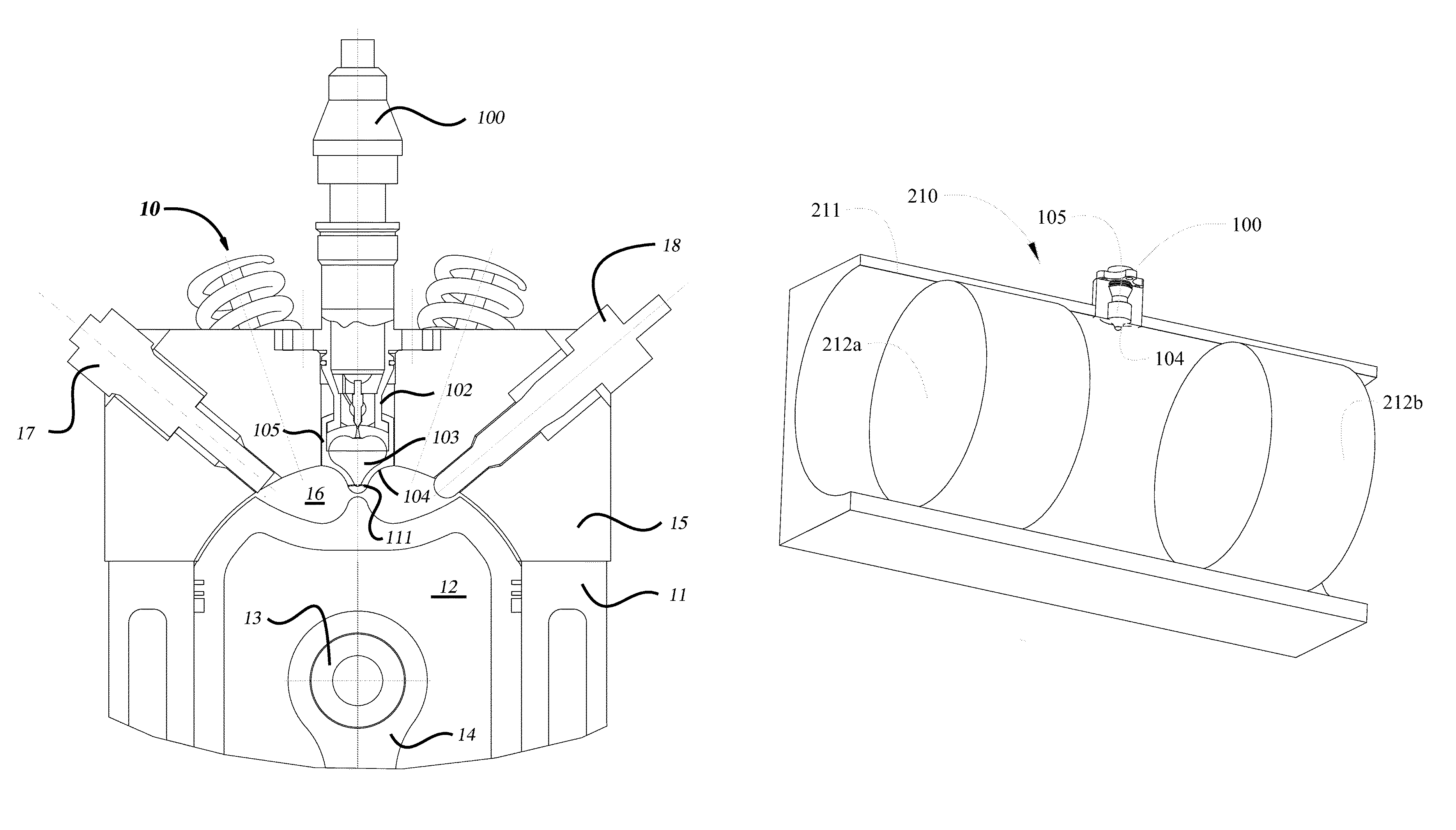
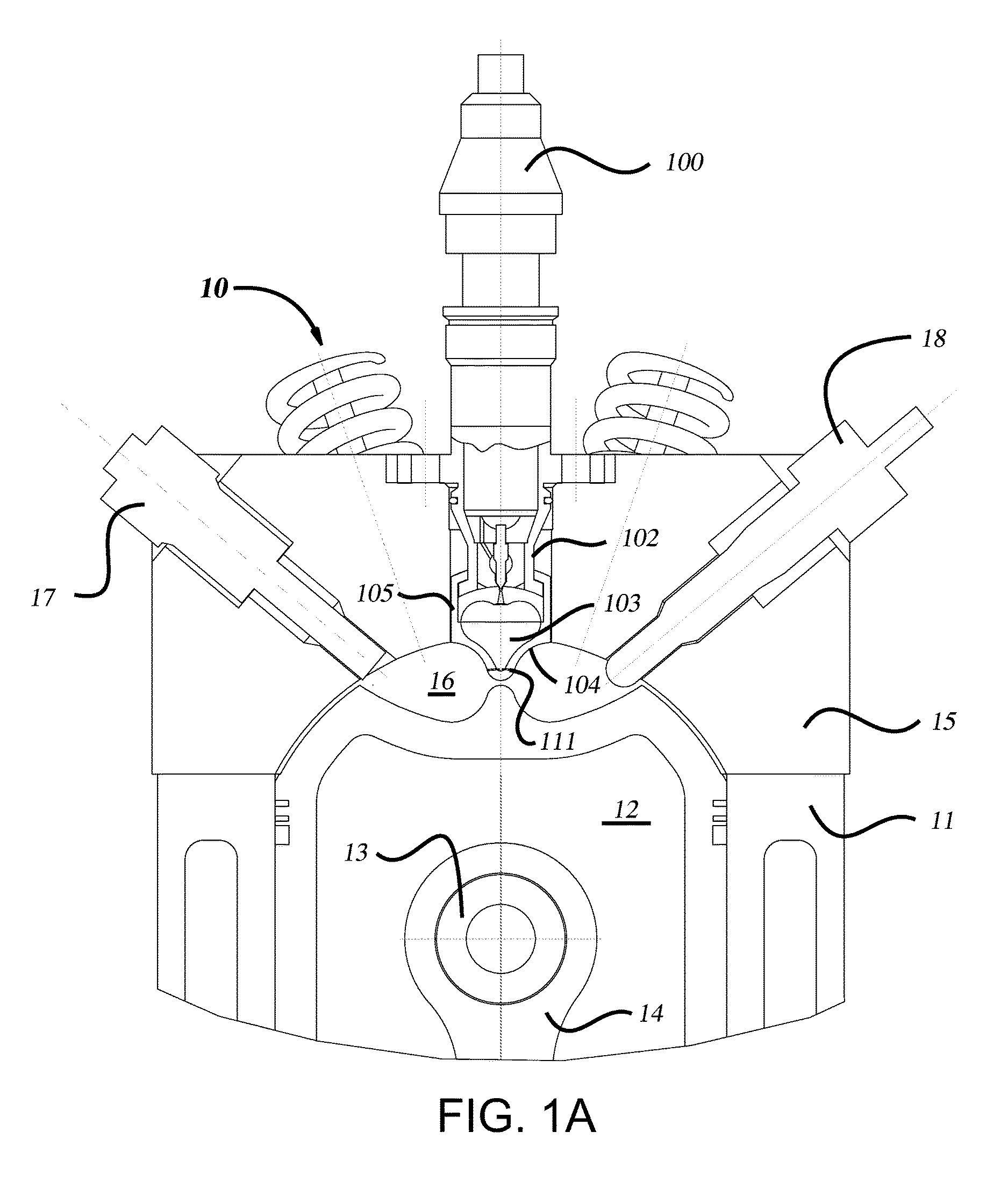
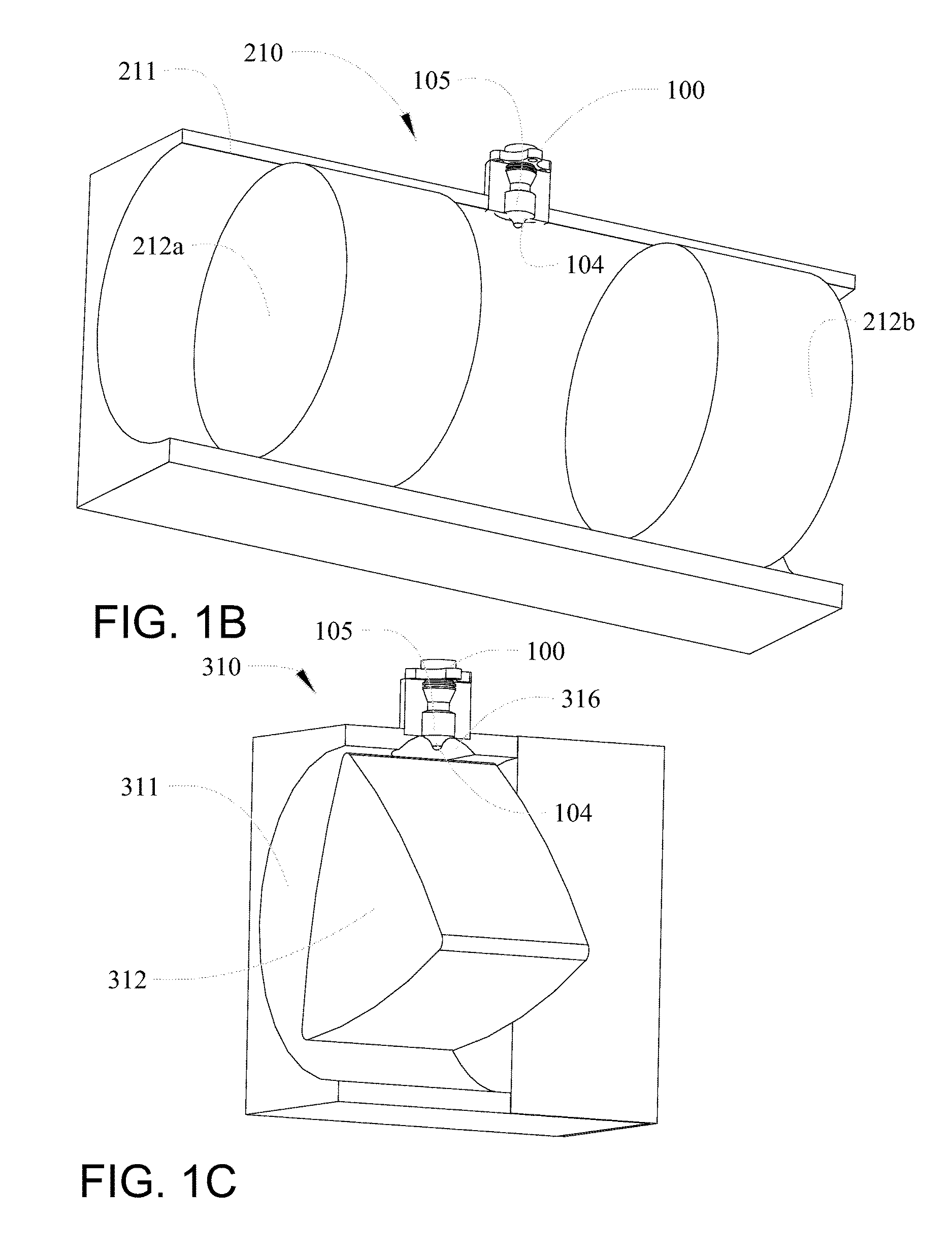
[0018]The embodiments disclosed herein provide a fuel conditioner and injector device which uses combustion heat energy for adiabatically heating and pressurizing a liquid fuel to above a critical point from a lower temperature and pressure of a liquid fuel delivery system prior to fuel entry into a combustion chamber of the engine. This process is referred to herein generally as “conditioning” of the fuel. An inlet injector includes a body receiving fuel under pressure from the fuel delivery system. Fuel is injected from the body through at least one liquid fuel inlet passage into a vessel having an expansion chamber. The liquid fuel flow is controlled by a conventionally activated valve as known in the prior art. The vessel has an exterior surface which is exposed within the combustion chamber and has an expansion chamber with the ability to withstand high pressure and high temperature. The vessel absorbs combustion heat through the exterior surface with heat transfer to the vesse...


PUM


Abstract

An internal combustion engine having a combustion chamber incorporates a fuel conditioner and injector employs a vessel having a wall exposed within the combustion chamber to be heated by combusting fuel. The vessel encompasses an expansion chamber and has at least one open fuel injection passage through the wall into combustion chamber. An inlet conduit receives liquid fuel at a predetermined pressure from a fuel delivery system. A nozzle interconnects the inlet conduit and the expansion chamber. A pin operably seals the nozzle for timed injection of liquid fuel into the expansion chamber. An operator actuates the pin from a closed position sealing the nozzle to an open position placing the fuel injection volume in fluid communication with the expansion chamber. Liquid fuel injected into the expansion chamber at a predetermined time is simultaneously adiabatically heated, and pressurized to a state above a critical point using heat in the vessel wall and self-injects through the at least one open fuel injection passage into the combustion chamber of the engine.

Description

BACKGROUND[0001]Field of the Invention[0002]The embodiments disclosed herein relate generally to fuel systems for an any internal combustion engines and more particularly to a fuel conditioning and injection system employing a volume in contact with combustion temperatures for adiabatic heating of fuel pumped into the chamber at a fuel rail pressure to high pressure and temperature and conversion of at least a portion of the fuel into more highly energized radical molecules for self-injection through open orifices into the combustion chamber of the engine. The open orifices allow partial oxidation of the fuel charge during adiabatic heating for formation of radicals improving combustion performance.[0003]References to Related Art[0004]Internal combustion engines, and more particularly compression-ignition engines, also known as a Diesel cycle engines, perform at maximum output and efficiency when the maximum combustion pressure occurs in a desired rotation range of the engine crank ...

Claims


Application Information

Patent Timeline
Patent Type & Authority Patents(United States)
IPC IPC(8): F02M31/14F02M31/18F02D41/38F02D41/40
CPCF02M31/145F02M31/18F02D41/3827F02D41/401F02B2019/002F02B2720/274F02D41/0025F02D41/003F02D41/3094F02D41/38Y02T10/12Y02T10/40
Inventor SERGIN, ALEXANDER
Owner SERGIN ALEXANDER
Why Eureka
Try Eureka