
Method and device for pumping of a process chamber

a technology of process chamber and pumping device, which is applied in the direction of cleaning process and equipment, cleaning of hollow articles, electrical equipment, etc., can solve the problems of increasing the operating pressure of vacuum limit, reducing reliability, and consuming non-negligible electrical power of pumps, etc., to achieve satisfactory pumping speed, low vacuum limit operating pressure, and easy and inexpensive

Active Publication Date: 2017-01-31
PFEIFFER VACUUM GMBH
View PDF10 Cites 6 Cited by
  • Summary
  • Abstract
  • Description
  • Claims
  • Application Information

AI Technical Summary

Benefits of technology

The present invention provides a pumping device that allows for easy and inexpensive low vacuum limit operating pressures and high pumping speeds for low-pressure processing of substrates. This is achieved by decreasing the flow rate of purging gas through the pumping stages of the dry primary vacuum pump and reducing the pressure at the outlet of the pump. The use of an ejector as the auxiliary pumping means allows for the desired pressure reduction without using moving parts, consuming no electrical power and requiring no maintenance. Additionally, ejectors are reliable, compact, and inexpensive.

Problems solved by technology

To guarantee that such vacuum limit pressures and such processing pressures one or two orders of magnitude higher can be obtained, one known means consists in increasing the number of pumping stages in the dry primary vacuum pumps so that they comprise for example six or seven stages, or in reducing the operating clearances of the pumps, thereby, in both cases, increasing their cost and tending to reduce their reliability.
However, these pumping devices are also expensive.
Nevertheless, the auxiliary pumps consume a non-negligible amount of electrical power and the vacuum limit operating pressure may prove to be insufficient.

Method used


Image

  • Method and device for pumping of a process chamber
  • Method and device for pumping of a process chamber
  • Method and device for pumping of a process chamber

Examples


first embodiment

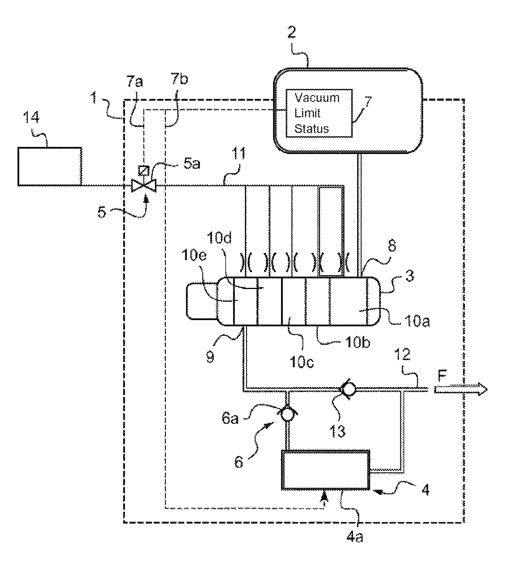
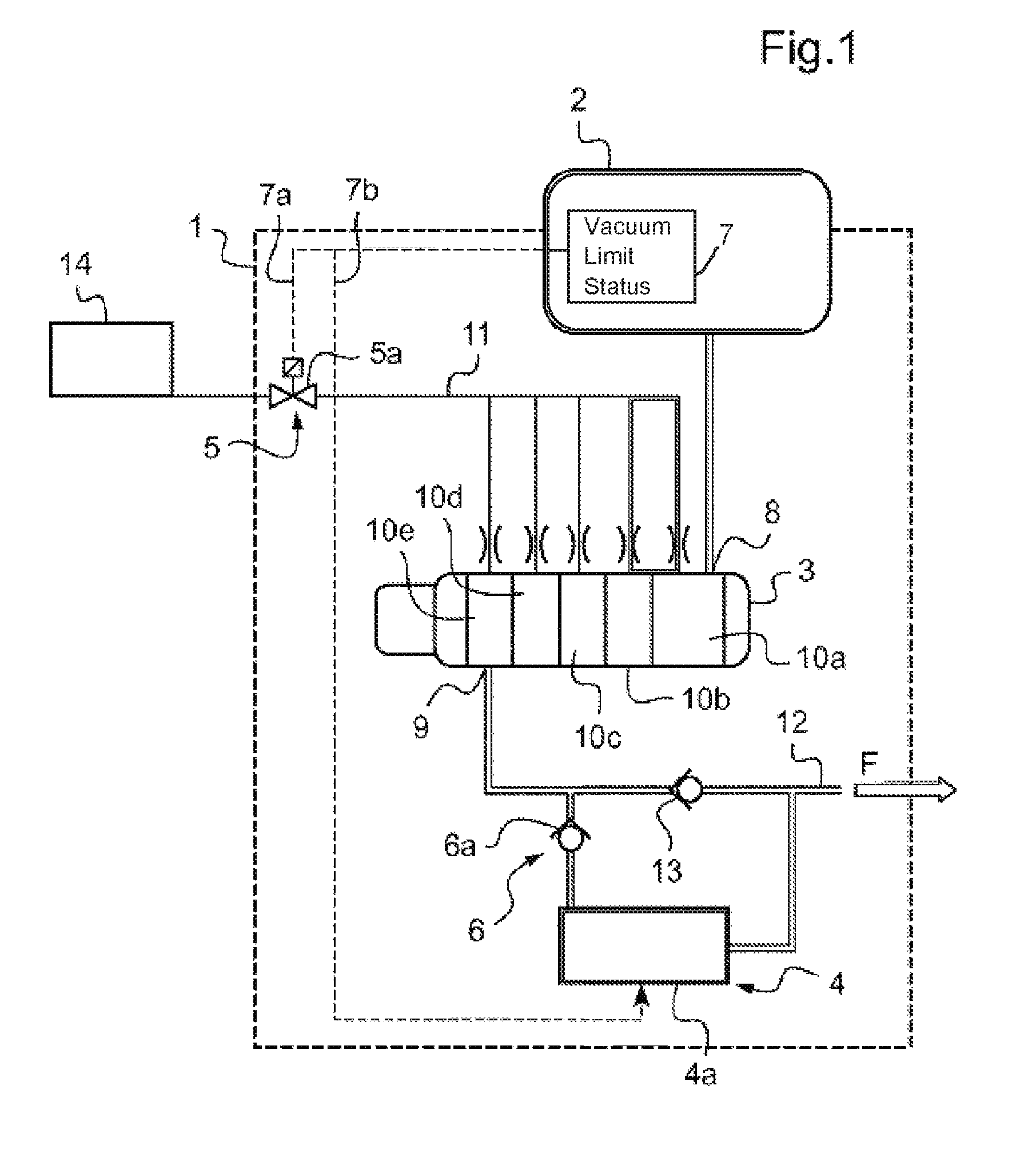
[0066]In the first embodiment in FIG. 1, the first valve-comprising device 5 is arranged on a common line of the distributor of the purging means 11 connecting all the branches of the dry primary vacuum pump 3. It thus decreases or cuts off the gas supply 14 to all the pumping stages 10a, 10b, 10c, 10d, 10e at the same time.

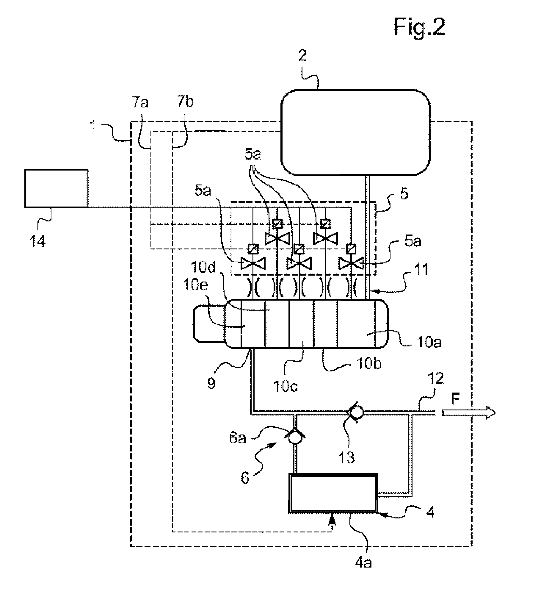
[0067]In another embodiment, shown in FIG. 2, the first valve-comprising device 5 is configured to selectively supply the pumping stages 10a, 10b, 10c, 10d, 10e with purging gas. For example, the first valve-comprising device 5 comprises as many solenoid valves 5a as the purging means 11 comprises branches, each solenoid valve 5a being arranged in a respective branch of the purging means 11 in order to selectively decrease or cut off the gas supply 14 to one or more pumping stages 10a, 10b, 10c, 10d, 10e at the same time.

[0068]The controlling means is for example configured to at least partially close those solenoid valves 5a of the first valve-comprising device ...

third embodiment

[0084]In a third embodiment shown in FIG. 3, the auxiliary pumping means 4 comprises an ejector 4b.

[0085]The ejector 4b comprises a duct 22 and a motive gas injecting means.

[0086]As may be more clearly seen in FIGS. 4a, 4b and 4c, the duct 22 comprises a suction orifice 16, an exhaust orifice 17 and at least one inlet nozzle 18a, 18b, 18c opening onto the interior space of the duct 22. The suction orifice 16 and the exhaust orifice 17 are connected to the exhaust duct 12 by first and second channels 19, 20 (FIG. 3), respectively. The means for injecting motive gas is configured to control injection of a pressurized motive gas, at high speed, into at least one inlet nozzle 18a, 18b, 18c.

[0087]In the example illustrated, the ejector 4b is a multistage ejector, i.e. it comprises a number of inlet nozzles 18a, 18b, 18c, distributed along the duct 22 between the suction orifice 16 and the exhaust orifice 17, defining a number of stages. The ejector 4b for example comprises three stages...

second embodiment

[0100]In a second embodiment, the first valve-comprising device 5 comprises a three-way valve 5b, such as a three-way solenoid valve, a first port being connected to the purging means 11 of the dry primary vacuum pump 3, a second port being connected to the gas supply 14, and a third port being connected to the means for injecting motive gas of the ejector 4b. Thus, control of the switch of the gas supply 14 from the dry primary vacuum pump 3 to the means for injecting motive gas of the ejector 4b, is simplified.

[0101]The second valve-comprising device 6 may comprise a calibrated anti-return valve 6a that automatically opens when the ejector 4b is started up. The controlling means is configured to start up the ejector 4b, i.e. to inject the motive gas into at least one inlet nozzle 18a, 18b, 18c, when the processing chamber 2 is in vacuum limit operation.

[0102]Alternatively, the second valve-comprising device 6 may comprise a solenoid valve 6b (FIG. 3).

[0103]Moreover, the second val...


PUM


Abstract

A pumping device intended to be connected to a process chamber (2) includes a dry primary vacuum pump, an auxiliary pump mounted so that the auxiliary pump bypasses a check valve on the vacuum pump, a first valve device connected to a purging device for purging the dry primary vacuum pump and intended to be connected to a gas supply, a second valve device mounted so that the second valve device bypasses a check valve upstream from the auxiliary pump, and a controller configured to control the first and second valve devices on the basis of an operating status of the process chamber in such a way that the first valve device is at least partially closed and the second valve device is open when the process chamber is operating at ultimate vacuum. Also a method for pumping of a process chamber by way of such a pumping device.

Description

CROSS REFERENCE TO RELATED APPLICATIONS[0001]This application is a National Stage of International Application No.[0002]PCT / EP2013 / 064929 filed Jul. 15, 2013, claiming priority based on French Patent Application No. 1202049 filed Jul. 19, 2012, the contents of all of which are incorporated herein by reference in their entirety.TECHNICAL FIELD[0003]The present invention relates to a pumping device comprising a dry primary vacuum pump for pumping a processing chamber, such as a processing chamber of a tool for fabricating semiconductors. The present invention also relates to a method for pumping by means of said pumping device.PRIOR ART[0004]Semiconductor substrate processing steps are carried out at low pressures in a processing chamber by means of a pumping device provided with a dry primary vacuum pump.[0005]A step carried out prior to the introduction of gases into the chamber for the processing of a substrate consists in checking the low-pressure threshold attainable in operation...

Claims


Application Information

Patent Timeline
Patent Type & Authority Patents(United States)
IPC IPC(8): F04B49/00H01L21/67F04B37/14F04C23/00F04C25/02F04C28/02F04F5/20B08B9/032F04C18/12F04C28/24F04C29/00
CPCH01L21/67011B08B9/0321F04B37/14F04C18/126F04C23/003F04C23/006F04C25/02F04C28/02F04C28/24F04C29/0092F04F5/20F04C29/0014F04C2220/30Y10T137/4259
Inventor SEIGEOT, BERTRAND
Owner PFEIFFER VACUUM GMBH
Learn More