Drain valve implantable in the eye of a patient for the treatment of glaucoma

a technology of glaucoma and drain valve, which is applied in the field of making a drain valve implantable in, can solve the problems of poor lubrication, increased or decreased pressure, and the surgeon cannot adapt to the drain valve, so as to reduce the performance and the effect of effectual remedying

Inactive Publication Date: 2017-02-07
ITH T3 PLUS
View PDF6 Cites 3 Cited by
  • Summary
  • Abstract
  • Description
  • Claims
  • Application Information

AI Technical Summary

Benefits of technology

[0020]Therefore the primary object of the present invention is to make a drain valve implantable in an eye for the treatment of glaucoma which is a significant improvement with respect to current valves, and in particular is suitable for effectively remedying the various and numerous disadvantages, such as those previously listed and discussed, which afflict in fact the known drain valves currently applied in the medical field for the treatment of glaucoma and therefore considerably limit the performances and the efficacy thereof.
[0021]A further object of the present invention is also that of making a drain valve for the treatment of glaucoma which can be implanted easily on the eye of a patient and offers moreover greater and wider possibilities of action for the surgeon during the phase of implant of the valve, with respect to the valves known and applied, and for example gives the possibility to the surgeon of varying and adapting, taking account of the specific configuration of the eye globe, the distance between the main body of the valve fixed on the surface of the eye globe, under the conjunctiva, and the point wherein the drainage tube is implanted with its tip in order to penetrate the interior of the eye globe.

Problems solved by technology

Now this particular circular shape in section of the drainage tube is such as to generate an encumbrance, on the ocular surface, which in turn is found to be the cause of discomfort for the patient in whom the valve has been implanted, given that this encumbrance hinders the movement of the eyelids which have to close and open often to lubricate the ocular surface.
In fact the drain valves currently available for the treatment of glaucoma do not appear such as to respond satisfactorily to some major needs and necessities which could arise and which the surgeon could have during the operation for implanting the drain valve.
For example known drain valves do not allow the surgeon to adapt, i.e. increase or decrease, the distance between the point wherein the drainage tube is implanted, and therefore penetrates the interior of the eye, and the valve itself, according to the specific circumstances and situations of the surgical operation to implant the valve in the eye of the patient.
Moreover a last but not least disadvantage, which can be found in known drain valves, is due to poor lubrication, in turn the potential cause of infections, which occurs in the zone of contact between the body of the drain valve and the outer surface of the eye globe whereon this body is implanted.
More particularly this considerable disadvantage occurs despite the fact that the main body of known drain valves is at times provided with several through holes which allow the placing in communication of the zone of the outer surface of the eye globe, on which the valve is placed and implanted, with the upper surface of the main body of the valve where the drained aqueous humour coming from inside the eye globe flows.
A further limit and disadvantage of known drain valves is connected to the fact that, in order to secure stably during the surgical operation the main body of the drain valve on the eye globe, the fixing holes, for the insertion of the yarn for fixing the main body of the valve on the outer surface of the eyeball, should be close, as far as possible, to the iris.
Instead, unfortunately, known drain valves have such a configuration as to involve a certain distance between these fixing holes and the iris, when it would instead be useful, for the reasons stated previously, i.e. to ensure more stable and robust attachment of the main body of the valve on the surface of the eye globe, for this distance to be smaller.

Method used


Image

  • Drain valve implantable in the eye of a patient for the treatment of glaucoma
  • Drain valve implantable in the eye of a patient for the treatment of glaucoma
  • Drain valve implantable in the eye of a patient for the treatment of glaucoma

Examples


Embodiment Construction

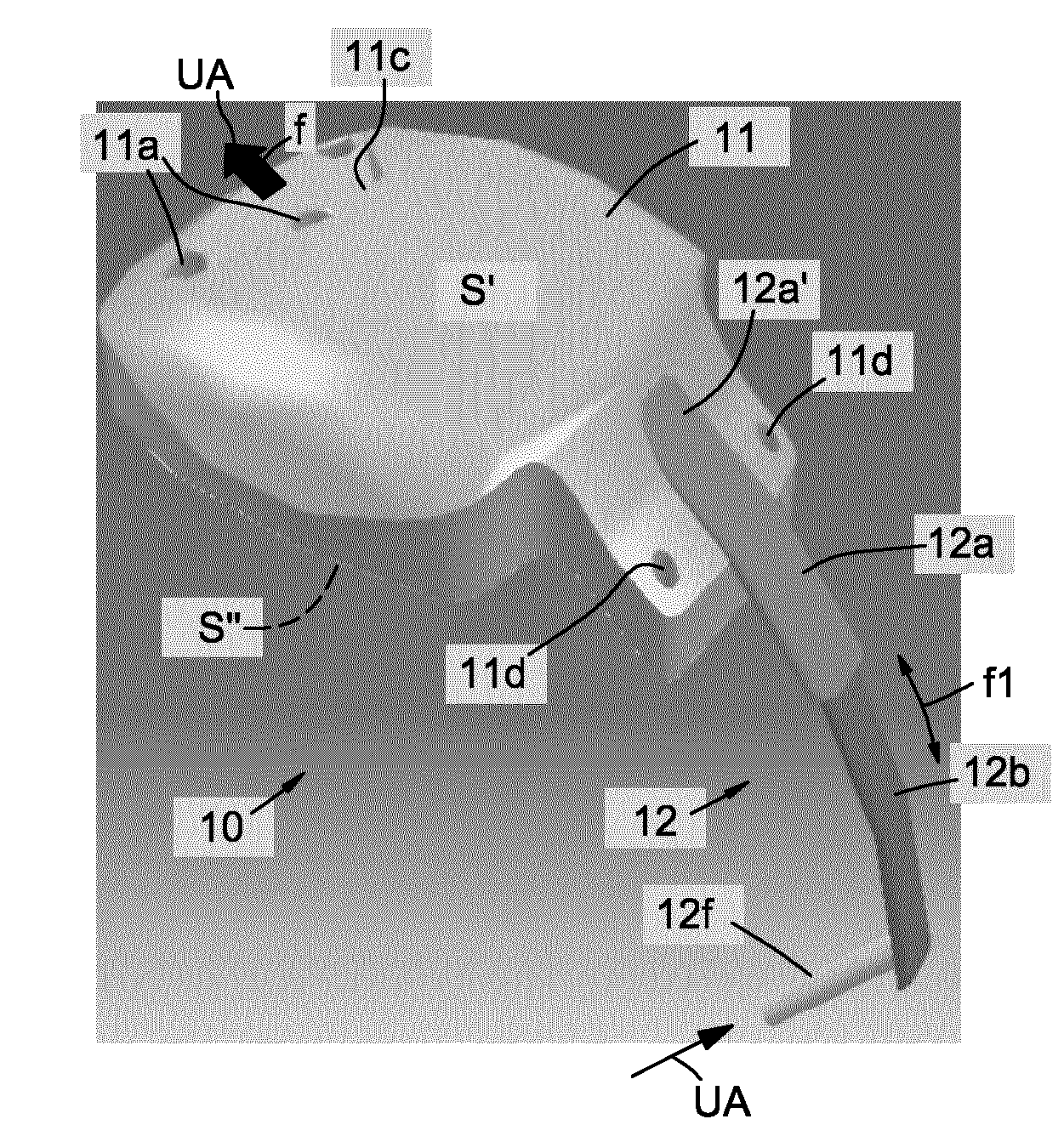
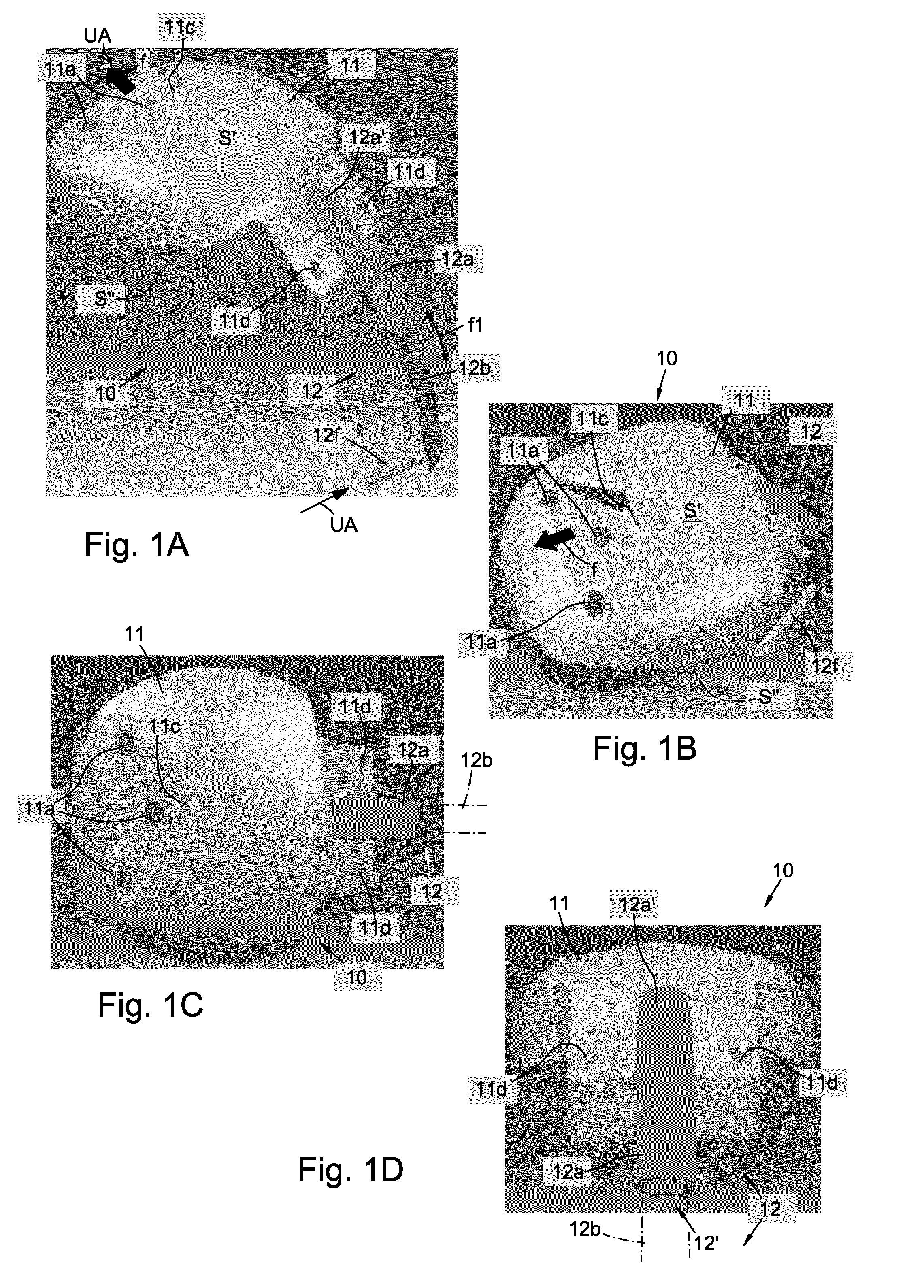
[0035]Referring to the drawings, a drain valve, in accordance with the present invention, implantable surgically in the eye O of a patient, in order to treat glaucoma, and in particular having the function of draining the aqueous humour UA contained in the anterior chamber CA of the eye globe GO, between cornea COR and iris IR, is denoted overall by 10.

[0036]For an easier and clearer understanding of the invention FIG. 9A shows schematically the zone of the eye O, with the parts previously mentioned, which is provided for receiving and in which is implanted the drain valve 10 of the invention.

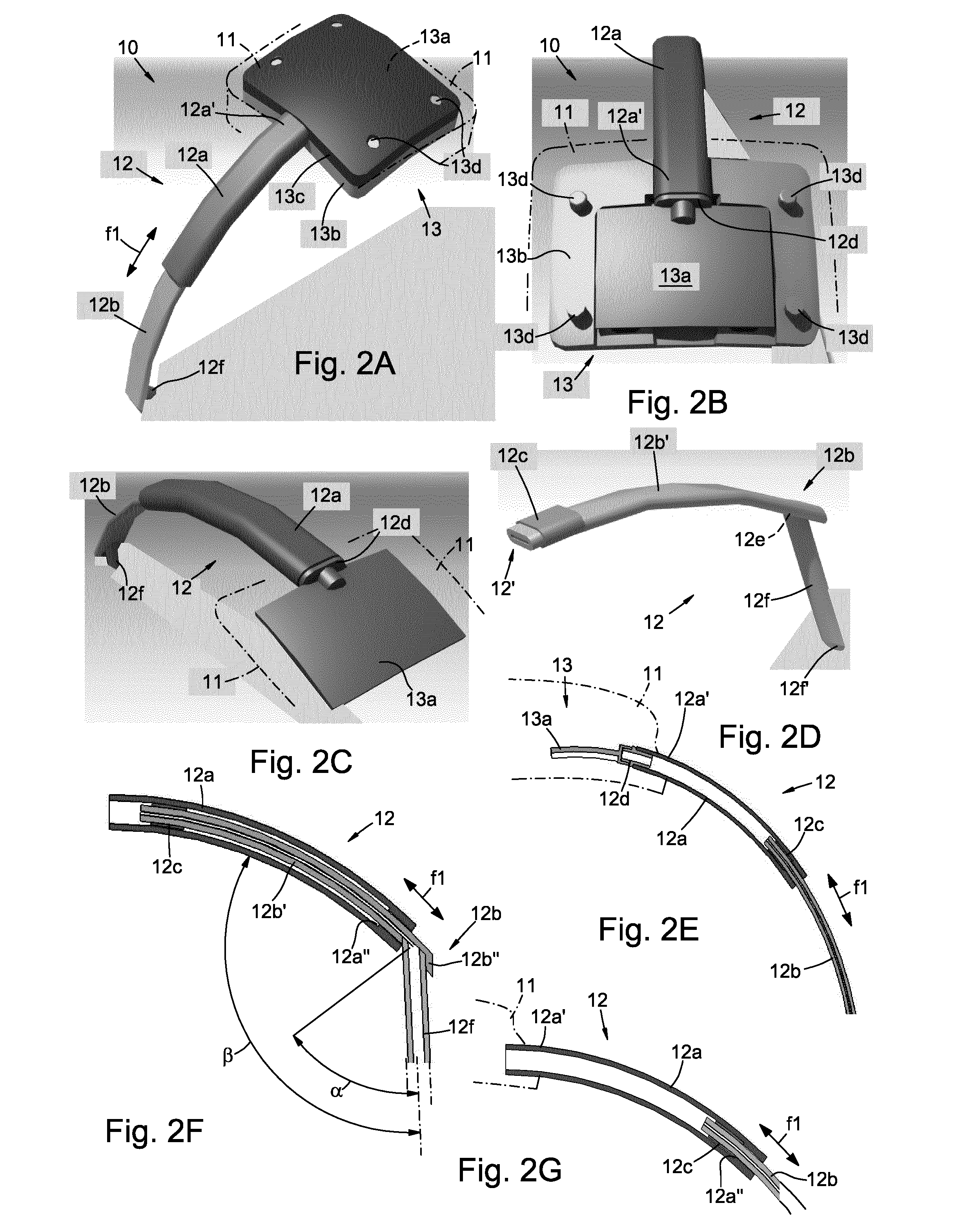
[0037]In detail the drain valve 10 comprises:[0038]a main body, denoted overall by 11; and[0039]a drainage tube, denoted overall by 12 and connected at one end with the main body 11.

[0040]The main body 11 is designed to be fixed by the surgeon on the outer surface of the eye globe GO of the eye O, incising the sclera or scleral sac SC in an area under the conjunctiva CON which covers the same e...


PUM


Abstract

A drain valve (10) implantable surgically in the eye (O) of a patient for the treatment of glaucoma, comprising a main body (11), and a drainage tube (12), connected at one end with the main body (11) and provided to be implanted in the eye (O) so as to penetrate with its distal tip inside the anterior chamber (CA) of the eye globe (GO), so as to allow the drainage outwards of the aqueous humour (UA), wherein the valve (10) is characterized by a series of significant improvements, including:1) an extractable configuration (12a, 12b) of the drainage tube (12), to allow the adaptation (f1) of the length of the drainage tube (12) during the surgical operation to implant the valve (10);2) a flattened or flat shape in section (12′) of the drainage tube (12, 12a, 12b) suitable for reducing the dimensions in the radial direction (IR) of the drainage tube (12) with respect to the surface of the eye globe (GO);3) a connection free from encumbrances between the tip portion (12f) of the drainage tube (12), provided to penetrate inside the eye globe (GO, CA), and the remaining part (12b′) of the drainage tube (12);4) a series of retaining bags or compartments (11b), formed along the lower or soffit surface (S″) of the main body (11) in contact with the surface of the eye globe (GO), wherein these retaining bags (11b) are associated with respective through holes (11a) extended through the same main body (11) of the valve and are suitable for receiving and retaining the aqueous humour (UA), so as to improve lubrication of the eyeball in the zone of the valve, once implanted;5) a divergent fan-shaped opening (11c) formed on the extrados (S′), not in contact with the eye globe, of the main body (11) of the valve, in order to convey the aqueous humour (UA) and improve the lubrication around the drain valve (10), once implanted; and6. a modified configuration, with respect to conventional drain valves, such as to allow, during the surgical operation, an arrangement, closer to the iris, of the holes (11d) for the insertion of the yarn for fixing the valve to the surface of the eye globe.Thanks to these improvements the drain valve (10) ensures considerably improved and superior performances with respect to the currently known drain valves in use in the medical field for treating glaucoma.

Description

[0001]This application is a U.S. national stage of PCT / IB2014 / 061378 filed on 12 May 2014, which claims priority to and the benefit of Italian Application No. MI2013A000783 filed on 13 May 2013, the contents of which are incorporated herein by reference in their entireties.DESCRIPTIONField of the Invention[0002]The present invention relates in general to the sector of implantable medical devices for the treatment and therapy of eye disease, and more particularly it relates to a drain valve suitable for being surgically implanted in the eye of a patient suffering from glaucoma in order to drain outwards the aqueous humour contained in the anterior chamber, between cornea and iris, of the eye, and therefore reduce the pressure of the aqueous humour inside the eye globe.BACKGROUND OF THE INVENTION AND PRIOR ART[0003]The prior art in the field of the invention offers implantable drain valves for the treatment of glaucoma which typically comprise a main body which in turn is associated w...

Claims


Application Information

Patent Timeline
Patent Type & Authority Patents(United States)
IPC IPC(8): A61M5/00A61F9/007
CPCA61F9/00781
Inventor TORELLO, GIULIORICCI, ALFREDO
Owner ITH T3 PLUS
Why Eureka
Try Eureka