Rotary wheel airtightness detecting machine

a technology of air tightness and detecting machine, which is applied in the direction of fluid tightness measurement, vehicle tyre testing, instruments, etc., can solve the problems of extreme wear of equipment, inability to conveniently and visually judge whether there is leakage at any circumferential position of the wheel, etc., to avoid severe abrasion of equipment, convenient and visually judge, and high degree of automation

Active Publication Date: 2017-02-07
CITIC DICASTAL
View PDF24 Cites 3 Cited by
  • Summary
  • Abstract
  • Description
  • Claims
  • Application Information

AI Technical Summary

Benefits of technology

[0005]The cylinder barrel, which is provided at its upper part with vents, is mounted on the upper platform and placed within the hollow shaft. The cylinder rod is connected with the piston with the spring placed under the latter, and the cylinder cover is mounted at the upper part of and within the cylinder barrel. All above components form a self-made air cylinder. In normal state, the spring is compressed and the guide flange on the top end of the cylinder rod is beneath the upper surface of the lower seal, which makes it convenient to clamp the wheel. Compressed air is filled from the lower end of the hollow shaft and enters the inner cavity of the wheel through the vents at the upper part of the cylinder barrel.
[0009]During use, the present invention can make the wheel be automatically centered between the upper seal and the lower seal, avoiding severe abrasion of equipment caused by inclination of the upper pressing plate for sealing upon biased positioning of the wheel. In addition, by rotating the wheel, the present invention makes it possible to conveniently and visually judge whether there is leak at any circumferential position of the wheel, and meanwhile possesses such characteristics as high degree of automation, sophisticated processing, safe and stable performance, etc.

Problems solved by technology

However, manufacturers presently use water airtightness machines without any wheel centering device, with the position of wheels being roughly determined only by human eyes.
When the conical upper seal presses downward, it has to be inclined to seal the front rim of the wheel tightly, which is extremely apt to wear the equipment.
In addition, the traditional water airtightness machines possess no function of rotating the wheel upon detection, making it impossible to conveniently and visually judge whether there is leak at any circumferential position of the wheel.

Method used


Image

  • Rotary wheel airtightness detecting machine
  • Rotary wheel airtightness detecting machine
  • Rotary wheel airtightness detecting machine

Examples


Embodiment Construction

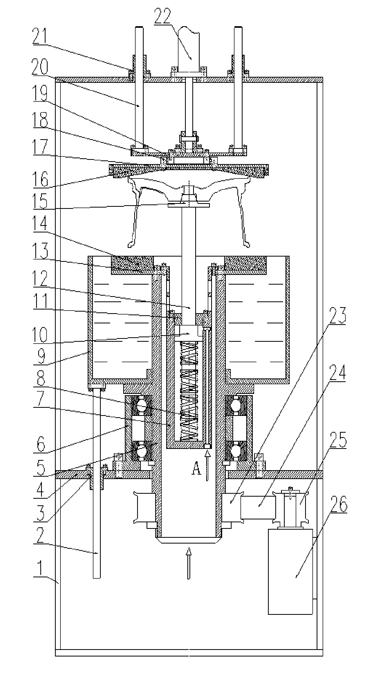
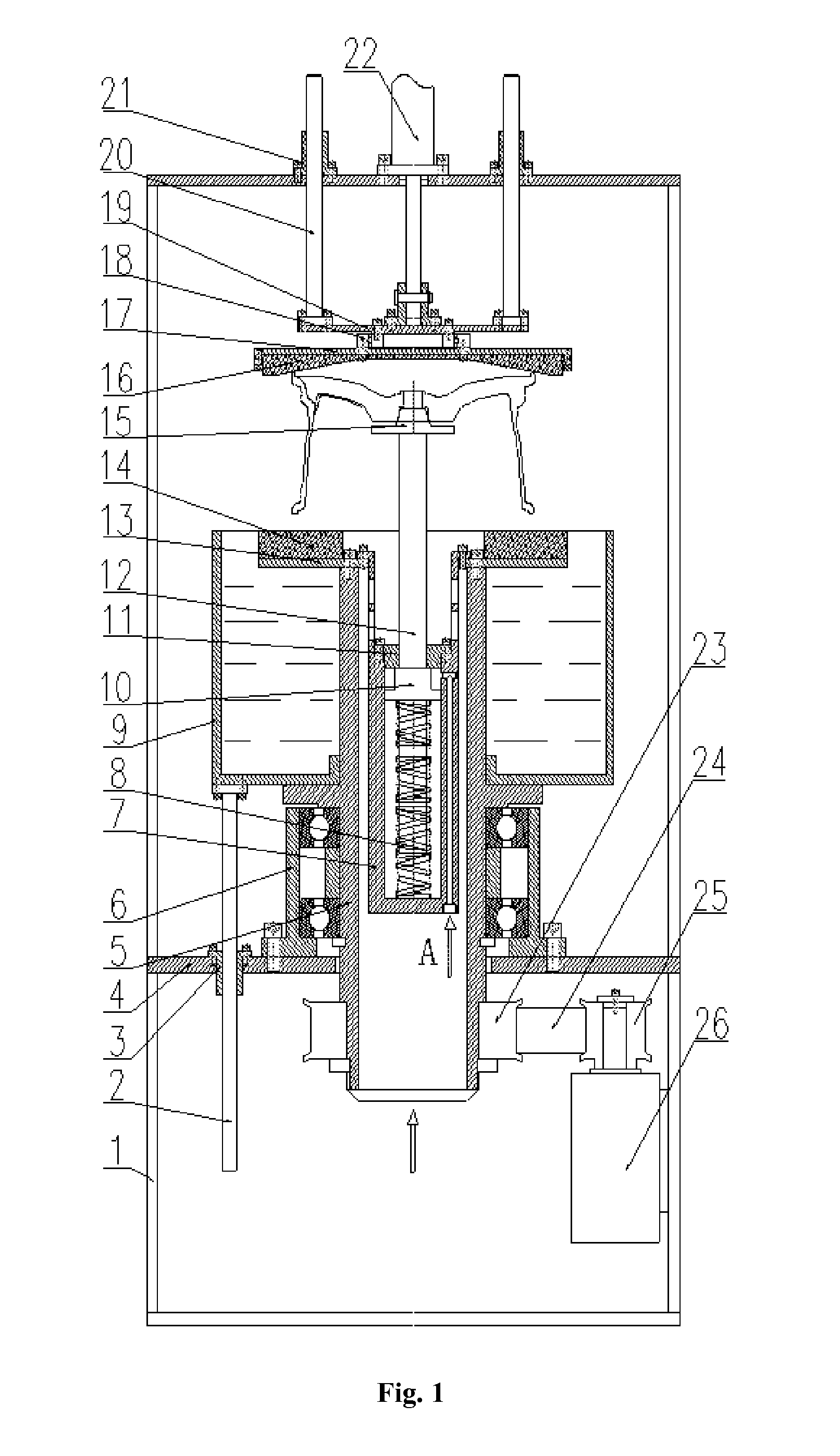
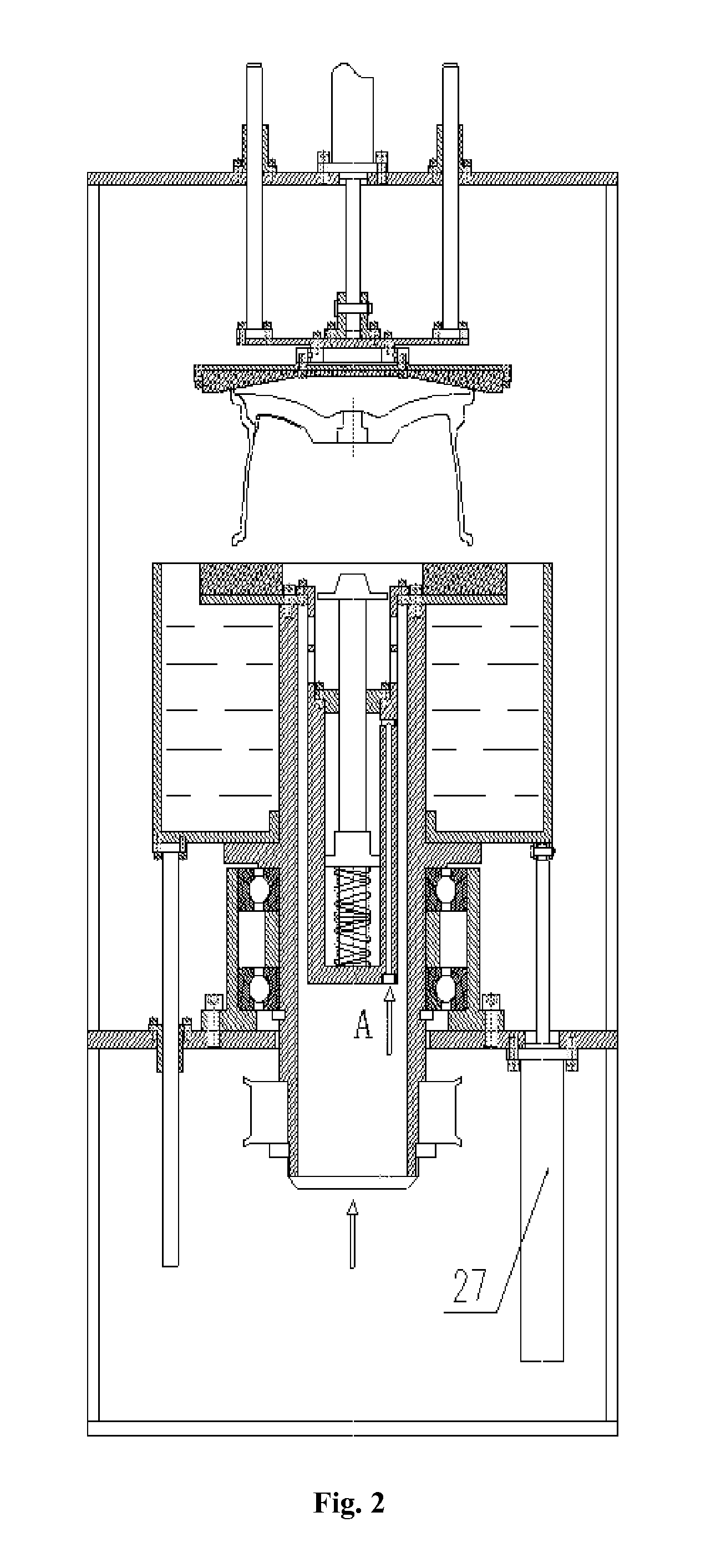
[0013]The details and operations of the specific device proposed by the present invention will now be described in conjunction with the drawings.

[0014]The device comprises a body frame 1, first guide pillars 2, first guide sleeves 3, a lower platform 4, a hollow shaft 5, a bearing block 6, a cylinder barrel 7, a spring 8, a water tank 9, a piston 10, a cylinder cover 11, a cylinder rod 12, an upper platform 13, a lower seal 14, a guide flange 15, an upper seal 16, a lower plate 17, a swivel 18, an upper plate 19, second guide pillars 20, second guide sleeves 21, a compressing cylinder 22, a first pulley 23, a synchronous belt 24, a second pulley 25, an electric motor 26 and a lifting cylinder 27. Four first guide sleeves 3 are fixed on the lower platform 4 and cooperate with four first guide pillars 2, the upper ends of which are fixed with the water tank 9. The output rod of the lifting cylinder 27, which is also fixed on the lower platform 4, is hinged with the bottom of the water...


PUM


Abstract

The present invention discloses a rotary wheel airtightness detecting machine which comprises a body frame, an air cylinder, an upper seal, a lower seal, a water tank, an electric motor and a self-made air cylinder, etc. During use, the present invention can make the wheel be automatically centered between the upper seal and the lower seal, avoiding severe abrasion of equipment caused by inclination of the upper pressing plate for sealing upon biased positioning of the wheel.

Description

TECHNICAL FIELD[0001]The present invention relates to an airtightness detecting machine, in particular to a machine for detecting airtightness by water.BACKGROUND[0002]In the process of manufacturing aluminum alloy wheels, the procedure of detecting airtightness is indispensable, which is directly related to driving safety. Therefore, manufacturers attach great importance to airtightness detecting procedure. Traditional methods for detecting airtightness include both airtightness detecting by water and airtightness detecting by helium gas. However, manufacturers presently use water airtightness machines without any wheel centering device, with the position of wheels being roughly determined only by human eyes. When the conical upper seal presses downward, it has to be inclined to seal the front rim of the wheel tightly, which is extremely apt to wear the equipment. In addition, the traditional water airtightness machines possess no function of rotating the wheel upon detection, maki...

Claims


Application Information

Patent Timeline
Patent Type & Authority Patents(United States)
IPC IPC(8): G01M3/26G01M17/02G01M3/10
CPCG01M17/021G01M3/103
Inventor BOWEN, XUEJIANDONG, GUOYANCHAO, RENWEIDONG, LIUYONGNING, WANGZHIHUA, ZHUCHANGHAI, LI
Owner CITIC DICASTAL
Why Eureka
Try Eureka