Drive coupling for high-speed rotating brush

a high-speed rotating brush and drive coupling technology, which is applied in the direction of couplings, carpet cleaners, cleaning machines, etc., can solve the problems of axially directed torque and axial force on the coupling member, and achieve the effect of eliminating axial play and sufficient clasping for

Active Publication Date: 2017-02-21
VERSUNI HLDG BV
View PDF15 Cites 0 Cited by
  • Summary
  • Abstract
  • Description
  • Claims
  • Application Information

AI Technical Summary

Benefits of technology

[0005]It is an object of the present invention to overcome or mitigate one or more of the above-mentioned problems associated with the known brush mount, in particular by providing a drive coupling that generates a sufficient clasping force and eliminates axial play only when the brush is being rotated.
[0007]In the presently disclosed drive coupling assembly, a force at a contact or interface point between a coupling head's drive surface and a coupling member's first drive surface is generated only when one of the parts of the drive coupling is driven to transfer a torque onto the other. Hence, when the drive coupling is at rest, no forces, and in particular no axial forces, are generated, which prevents long term creep effects and the development of imbalances in the drive coupling. This effect is accomplished by a suitable configuration of the drive surfaces of the coupling head and the first drive surfaces of the coupling member, which are configured for mutual pairwise cooperation. If these drive surfaces are assumed to be generally smooth and continuous, and contact between each pair of them is additionally assumed to occur at a single contact point, the laws governing the surface contact prescribe that at the point of contact both a common normal and a common tangent exist, and that (in the absence of friction between the smooth surfaces) forces are transferred only along the common normal. Consequently, the first drive surfaces of the coupling member may, for example, be shaped such that each point of said surfaces is associated with a surface normal having both a non-zero component in the axial direction and a non-zero component in the tangential direction (both with respect to the coupling member's rotation axis), thus allowing the surface to sustain both an axially directed force along, and a torque around the coupling member rotation axis. Alternatively, or in addition, the same may mutatis mutandis apply to the drive surfaces of the coupling head. When a thus configured drive coupling is inserted between a transmission and a rotatably mounted brush, both of which may be fixedly attached to a respective part of the drive coupling, driving the brush via the drive coupling will provide an axial clasping force on the brush, which clasping force will squeeze axial play out of the system.
[0009]A radially centering force provides additional stability to a drive coupling assembly that rotates at high rotational speeds, and may be sustained by drive surfaces with a surface normal having a non-zero component in the radial direction. The first drive surfaces of the coupling member may, for example, be shaped such that each point of said surfaces is associated with a surface normal having a non-zero component radial direction with respect to the coupling head rotation axis. Alternatively, or in addition, the same may mutatis mutandis apply to the drive surfaces of the coupling head.
[0013]The coupling member may thus include six drive surfaces, dividable in three mirror symmetric pairs, each pair including a first and a second drive surface. Both the first drive surfaces and the second drive surfaces may be arranged to be rotationally symmetrical through 120 degrees with respect to the rotation axis of the coupling member. Due to this combination of rotational and mirror symmetry in the configuration of the coupling member's drive surfaces, the coupling member may be arbitrarily driven clockwise and anti-clockwise to generate the same axial and centering forces. From a practical point of view, this makes oppositely rotating brushes fitted with mutually identical coupling members interchangeable, so as to facilitate their replacement and prevent the need for separately manufactured clockwise and anti-clockwise drivable coupling members.

Problems solved by technology

Furthermore, the drive surfaces of the coupling head and the first drive surfaces of the coupling member are configured such that driving the former in contact with the latter results in the exertion of both a torque and an axially directed force on the coupling member.

Method used


Image

  • Drive coupling for high-speed rotating brush
  • Drive coupling for high-speed rotating brush
  • Drive coupling for high-speed rotating brush

Examples


Embodiment Construction

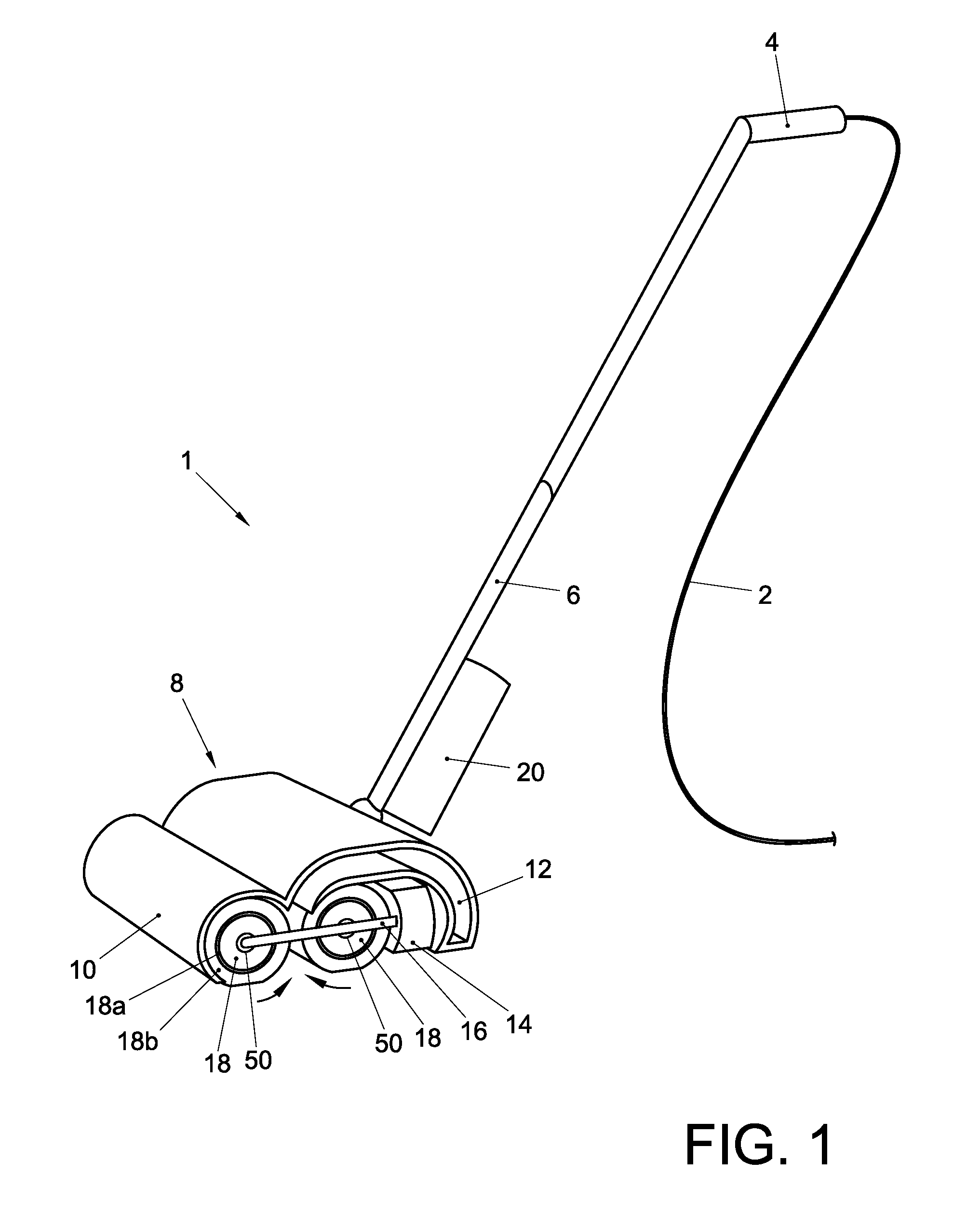
[0021]FIG. 1 is a perspective view of an exemplary hard floor cleaning device 1 according to the present invention. The device 1 may include a handle 4, which may be connected to a housing 8 via a connection rod 6. The housing 8 may accommodate two high-speed rotating brushes 18. Each brush 18 may include an elongate, substantially cylinder jacket-shaped core 18a whose outer surface is covered with a brush material 18b, e.g. soft microfiber filaments. At its axial ends, each brush 18 may be rotatably mounted in the housing 8 around its longitudinal axis. The housing 8 may further accommodate a motor mechanism 14, 16 that is configured to drive each of the brushes 18 into rotation at a rotational speed of at least 2,500 rpm. The motor mechanism may include an electromotor 14 for generating a driving force / torque, and a transmission 16 for transferring the driving force / torque to the brushes 18, each time via a drive coupling 50 that is disposed between a respective brush 18 and the t...


PUM


Abstract

Drive coupling assembly (50) for a high-speed rotating brush, comprising:—a coupling head (100) having a coupling head rotation axis (Lch) and including three drive surfaces (106) which are arranged to be rotationally symmetrical through 120° with respect to said coupling head rotation axis; and—a coupling member (200), having a coupling member rotation axis (Lcm) and including three first drive surfaces (210a) which are arranged to be rotationally symmetrical through 120° with respect to said coupling member rotation axis, wherein said coupling head (100) and said coupling member (200) are detachably couplable, such that, in a coupled condition, their rotational axes (Lch, Lcm) are aligned and the coupling head is rotatable to drive each of its drive surfaces (106) in contact with a respective first drive surface (210a) of the coupling member, to thereby exert both a torque and an axially directed force on the coupling member.

Description

CROSS-REFERENCE TO PRIOR APPLICATIONS[0001]This application is the U.S. National Phase application under 35 U.S.C. §371 of International Application No. PCT / IB2012 / 053849, filed on Jul. 27, 2012, which claims the benefit of U.S. Provisional Patent Application No. 61 / 522,265, Aug. 11, 2011 and European Patent Application No. 11177194.5, filed on Aug. 11, 2011. These applications are hereby incorporated by reference herein.FIELD OF THE INVENTION[0002]The present invention relates to the field of hard floor cleaning devices, and more in particular to a drive coupling for a high-speed rotating brush of such a cleaning device.BACKGROUND[0003]A hard floor cleaning device may include one or more high-speed rotating brushes. Each brush may have an elongate cylindrical core, extending axially between a first end and a second end, whose outer surface is covered with a brush material, e.g. soft microfiber filaments. The first and second ends of the brush may be bearingly mounted in the cleanin...

Claims


Application Information

Patent Timeline
Patent Type & Authority Patents(United States)
IPC IPC(8): F16D1/108A47L11/40F16D1/10
CPCF16D1/108A47L11/4069F16D1/10F16D1/101F16D2001/102Y10T403/7039F16B2200/10
Inventor DE WIT, BASTIAAN JOHANNESWIERDA, WIEBEVOORHORST, FOKKE ROELOF
Owner VERSUNI HLDG BV
Why Eureka
Try Eureka