Motorized vacuum isolation switch

a motorized vacuum and isolation switch technology, which is applied in the direction of switchgear with a retractable carriage, switch power arrangements, contact mechanisms, etc., can solve the problems of the size and weight of the draw out cell/contactor pan of the contactor equipmen

Active Publication Date: 2017-02-21
BECKER MINING AMERICA
View PDF10 Cites 14 Cited by
  • Summary
  • Abstract
  • Description
  • Claims
  • Application Information

AI Technical Summary

Benefits of technology

[0040]The attachment assembly can include two spring loaded contactor bucket interlock plunger pins, one on each of the right and left front sides of the movable contactor pan that mate with corresponding apertures in the front side panels of the contactor bucket to allow ...

Problems solved by technology

A problem with prior art switchgear, circuit interrupters and contactor equipment is t...

Method used


Image

  • Motorized vacuum isolation switch
  • Motorized vacuum isolation switch
  • Motorized vacuum isolation switch

Examples


Embodiment Construction

[0068]Before explaining the disclosed embodiments of the present invention in detail it is to be understood that the invention is not limited in its application to the details of the particular arrangements shown since the invention is capable of other embodiments. Also, the terminology used herein is for the purpose of description and not of limitation.

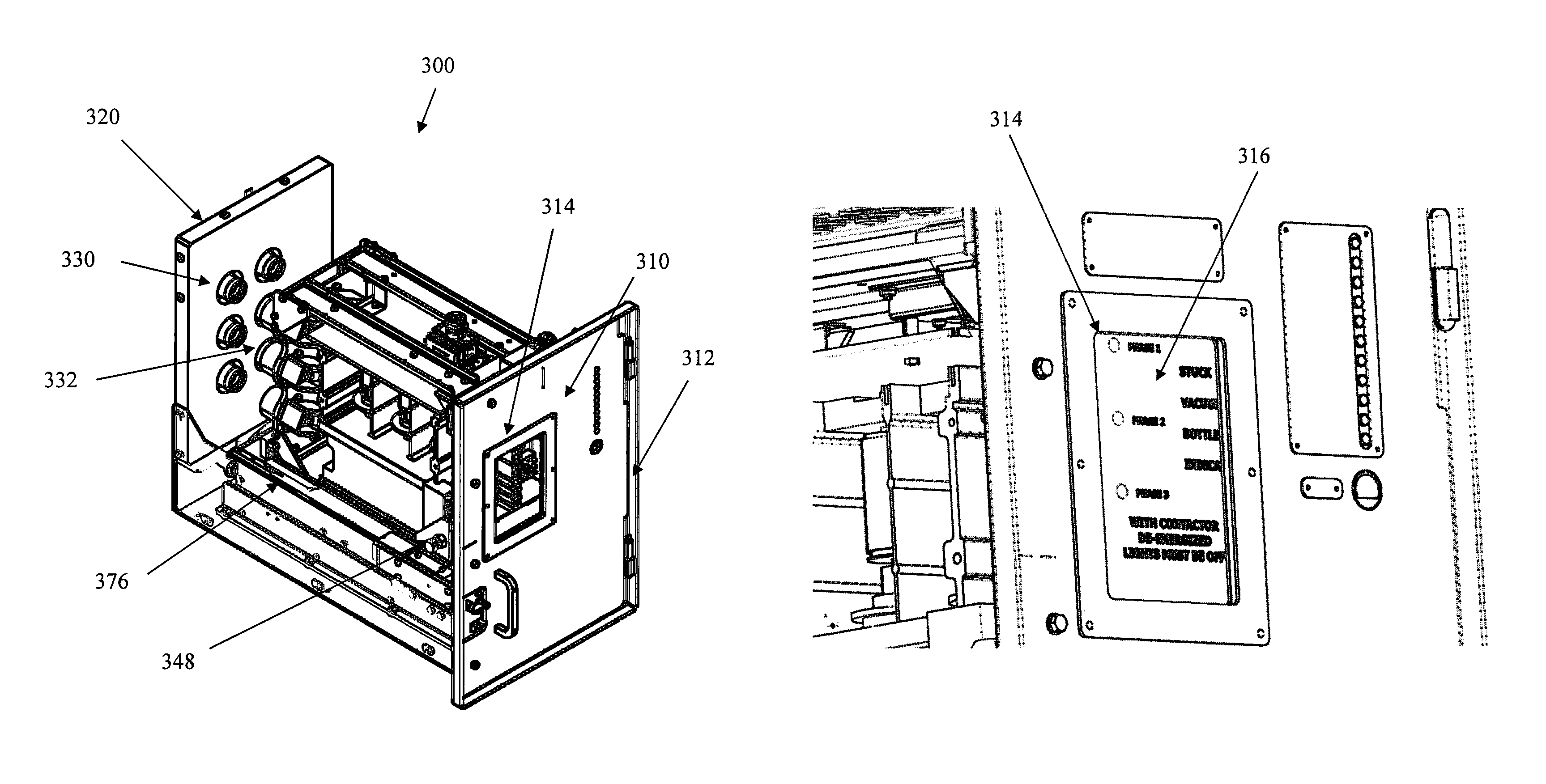
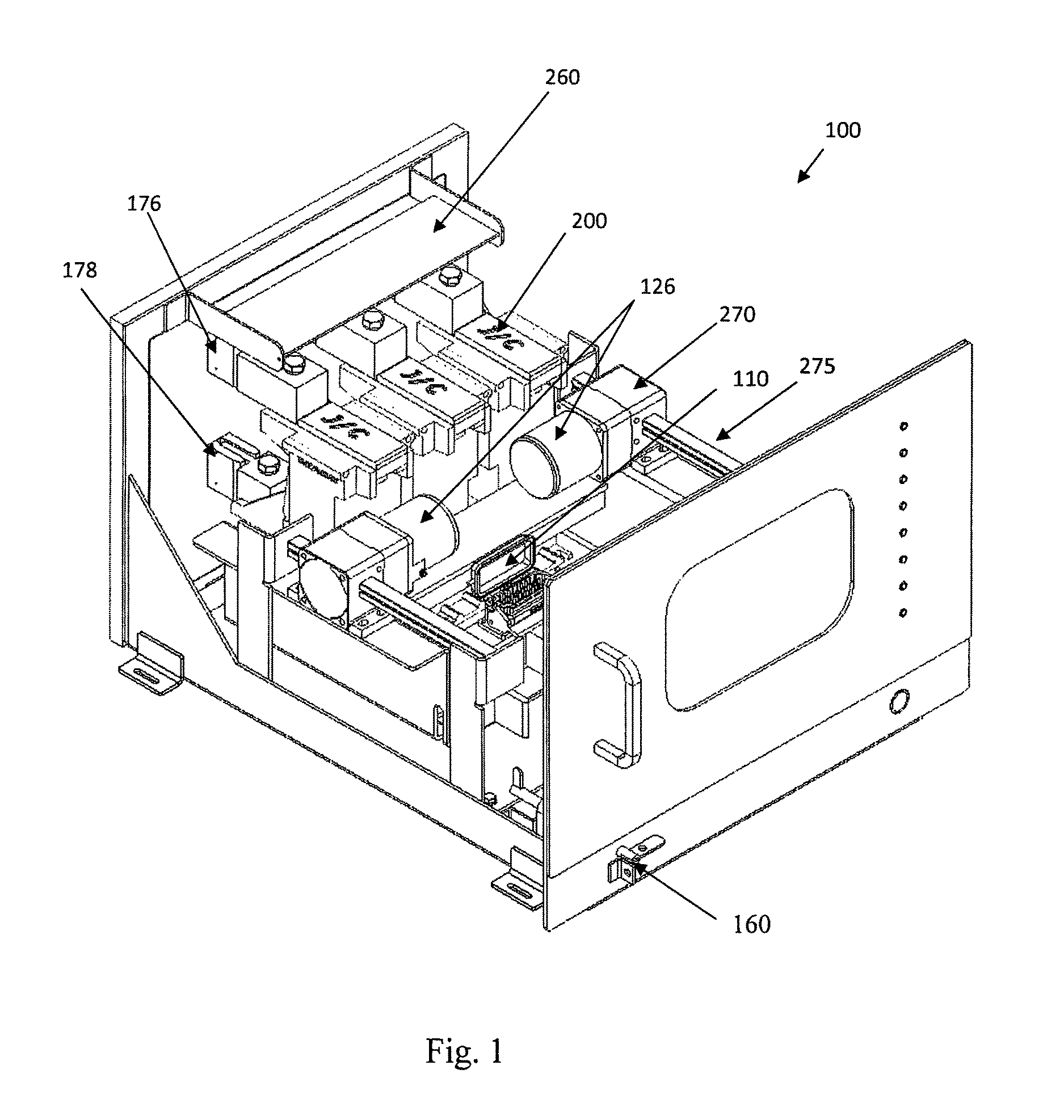
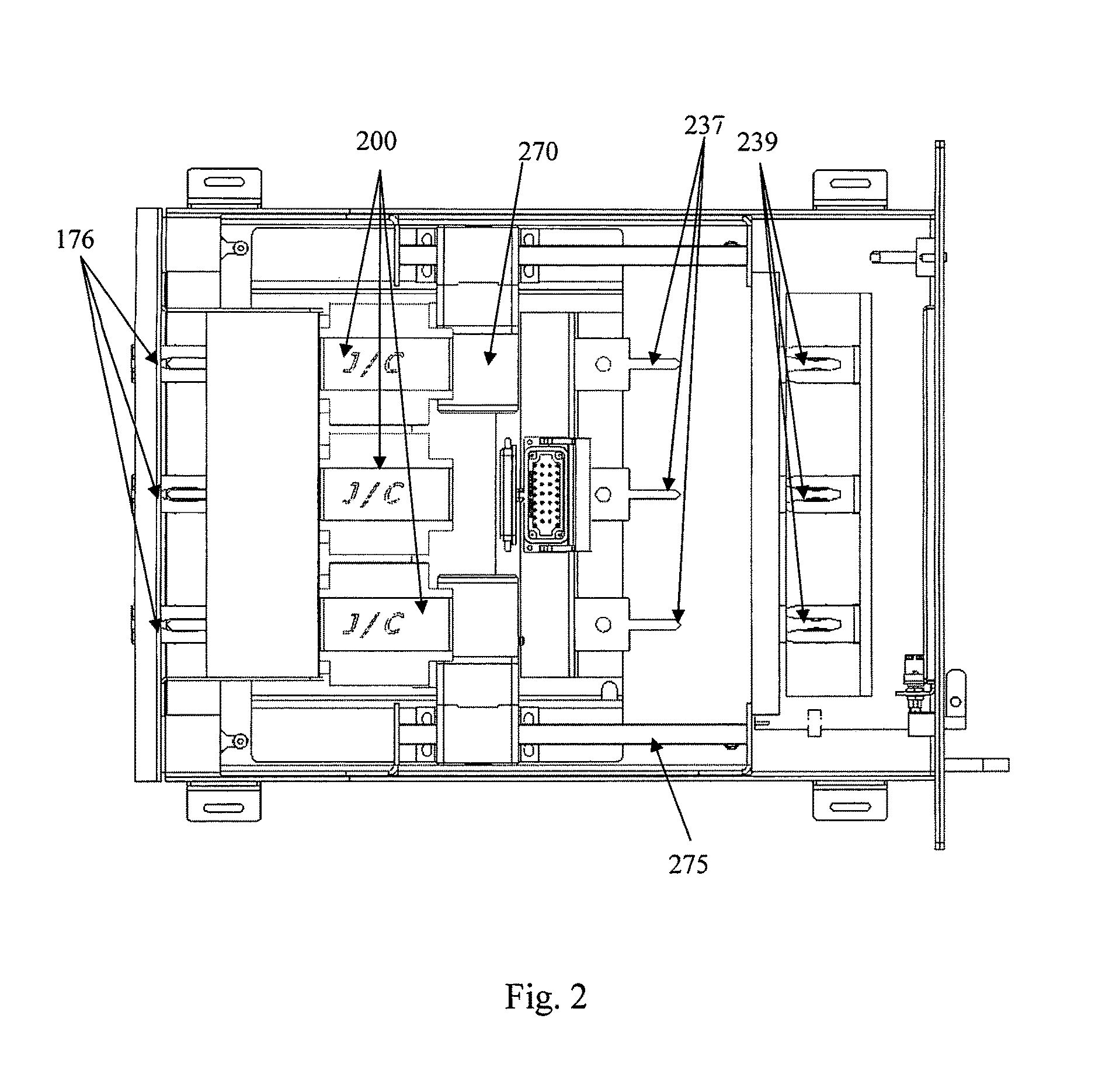
[0069]The following is a list of reference numerals used in the description and the drawings to identify components:[0070]100 removable motor power cell[0071]110 controller signal connector[0072]126 motor[0073]140 rack and pinion assembly[0074]160 lock out assembly[0075]162 lock out lever—rotatable[0076]164 lock out shaft[0077]176 interior stationary upper multi-fork (incoming)[0078]177 movable incoming power blade[0079]178 interior lower multi-fork (outgoing)[0080]179 movable outgoing load blade[0081]200 circuit interrupter[0082]210 bus bar[0083]220 visible disconnect switch blade[0084]230 multi-fork connector (closed and energized)...


PUM


Abstract

Methods, systems, devices for a motorized isolation switch including a switch enclosure with a set of fixed insulated floating input line connectors and output load connectors movably fixed to the rear panel, a removable contactor bucket insertable into the isolation switch enclosure with mating movable insulated line terminals and load terminals and a set of insulated circuit interrupters, a motorized rack and pinion assembly connected to a base of the switch enclosure, coupled for moving a contactor pan connectable to the contactor bucket along a stationary rack gear along the base of the switch enclosure between and switch open position and a switch closed position, an insulating grounding block with ground connectors, the contactor bucket with corresponding movable ground terminals to mate with the insulated ground connectors in the switch open position, and ancillary controls for communicating with remotely located controls to electrically control the operation.

Description

[0001]This applicant is a continuation-in-part of U.S. patent application Ser. No. 14 / 033,016 filed on Sep. 20, 2013 which claims the benefit of priority to U.S. Provisional Application No. 61 / 703,459 filed on Sep. 20, 2012. The entire disclosure of each of the applications listed in this paragraph are incorporated herein by specific reference thereto.FIELD OF THE INVENTION[0002]This invention relates to rack mountable electrical switching equipment and, in particular, to methods, systems and devices for an insulated motorized vacuum isolation switch for connecting and disconnecting high voltage electrical power with an electro-mechanical lockout mechanism operated using an automatic or remotely operated power switching assembly coupled with the motorized vacuum isolation switch.BACKGROUND[0003]Switchgear is the aggregate of switching devices for a power or transforming station or for electric motor control. A bus is provided, to which are connected the generator (source) and the fe...

Claims


Application Information

Patent Timeline
IPC IPC(8): H02B11/02H01H3/26H01H9/16H01H9/24H02B11/28H02B11/00H02B11/10
CPCH01H3/26H01H9/16H01H9/24H02B11/02H02B11/28H02B11/00H02B11/10H01H2003/266H01H9/161H02B1/36H02B11/133
Inventor HANDSHOE, SAM
Owner BECKER MINING AMERICA
Why Eureka
Try Eureka