Lightweight marine craft and methods thereof

a marine craft and light-weight technology, applied in the field of light-weight marine craft, can solve the problems of increasing cost, increasing labor, and still relatively heavy, and achieve the effect of reducing pull and lateral resistance of the sailboat hull

Active Publication Date: 2017-02-28
BETTA BOATS LLC
View PDF10 Cites 4 Cited by
  • Summary
  • Abstract
  • Description
  • Claims
  • Application Information

AI Technical Summary

Benefits of technology

[0015]Lateral resistance for a sailboat hull can be provided by telescoping leeboards, one on each side of the hull, tied to the hull using the rope tie attachment described above. A weight on the lower leaf of the leeboard pulls that leaf downward, providing a deeper extension of the center of lateral resistance to reduce the pull to windward and the heeling moment on the hull. This lower leaf of the telescoping leeboard can be pulled up when sailing down wind or in shallow waters.

Problems solved by technology

These molds and substrates, and the extensive labor required to apply and finish fiberglass, add to cost.
While fiberglass boats have offered durability and other performance advantages compared to their wood or metal predecessors, they are still relatively heavy.
More recently, carbon fiber has been used in place of fiberglass, lowering weight but adding cost.

Method used


Image

  • Lightweight marine craft and methods thereof
  • Lightweight marine craft and methods thereof
  • Lightweight marine craft and methods thereof

Examples


first embodiment

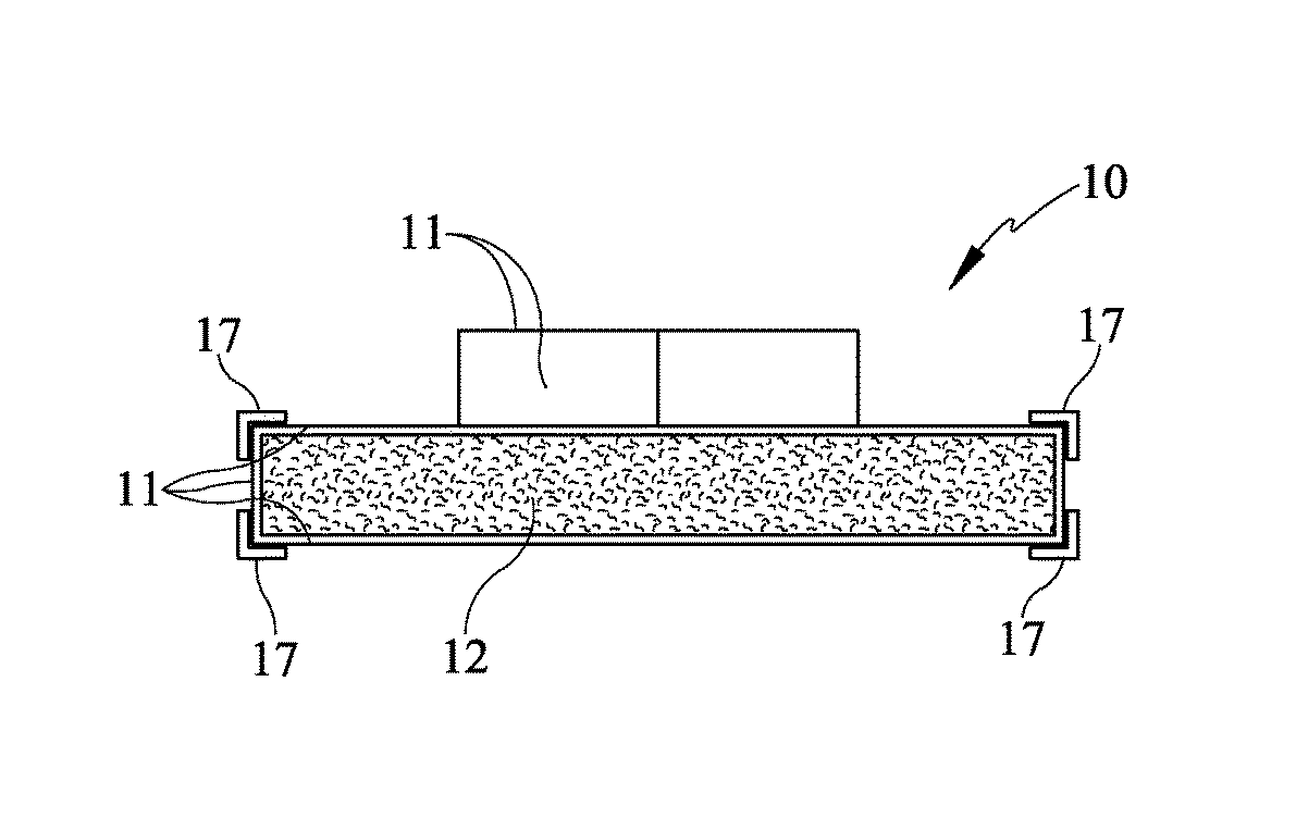
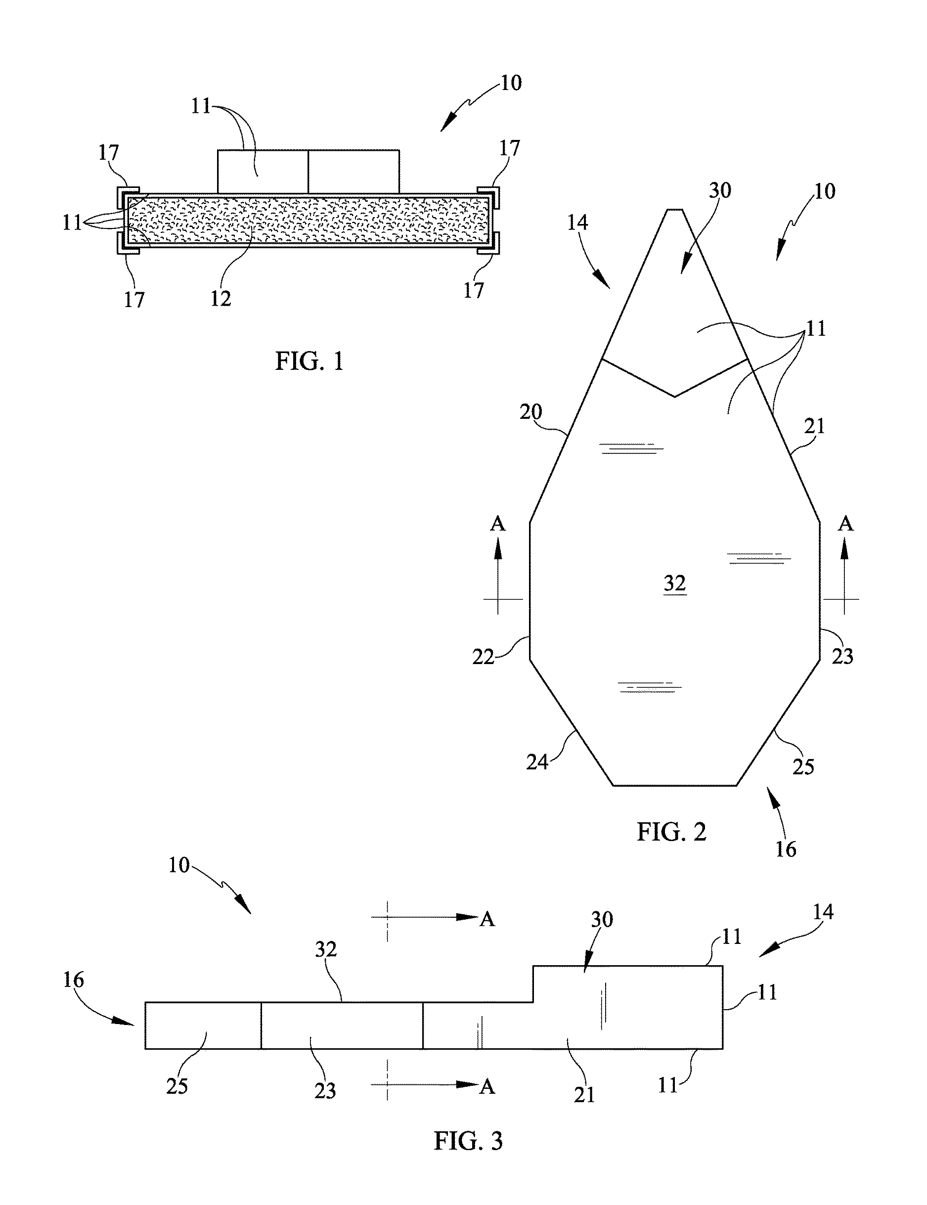
[0039]According to FIG. 5a, a through-deck rod 40 may be utilized. In this embodiment, the hull 10 shown formed by the core 12 and includes a skin 11 wrapped about the core 12. In this embodiment, a through-deck threaded rod 40 extends through the skin 11, core 12 and through the opposite side of the hull 10. The threaded rod 40 is defined by a screw or other such fastener and includes a washer 42 at upper and lower ends thereof to engage the skin 11, or alternatively the core 12. The rod 40 may be threaded such that a nut 44 may be applied at the lower side of the hull 10 and against the washer 42. An insert or sleeve 46 may extend through the core 12 and provide a pathway for the rod 40 to pass there through. The insert 46 may be hollow in shape to allow passage of the rod 40 and may have various cross-sectional shapes. A plate 150 may be disposed on the upper surface of the core 12 or skin 11 and beneath the upper washer 42 to mount other items, such as masts, cables, ropes or sh...

second embodiment

[0040]Referring now to FIG. 5b, a second embodiment for connecting fittings is depicted in side section view. In this embodiment, a plate 150 is fastened to the core 12. The fasteners 140 may be of the self-tapping variety that extend into the core 12 and retain the plate 150 against the hull 10. The plate 150 further comprises at least one fastener 146 to retain a fitting 142 on an upper surface of the plate 150. The fitting 142 allows for retaining of various structures including tube, cable or rope structures by providing connection to the hull 10. These attachments and related methods allow attachment of fittings and equipment to the hull 10.

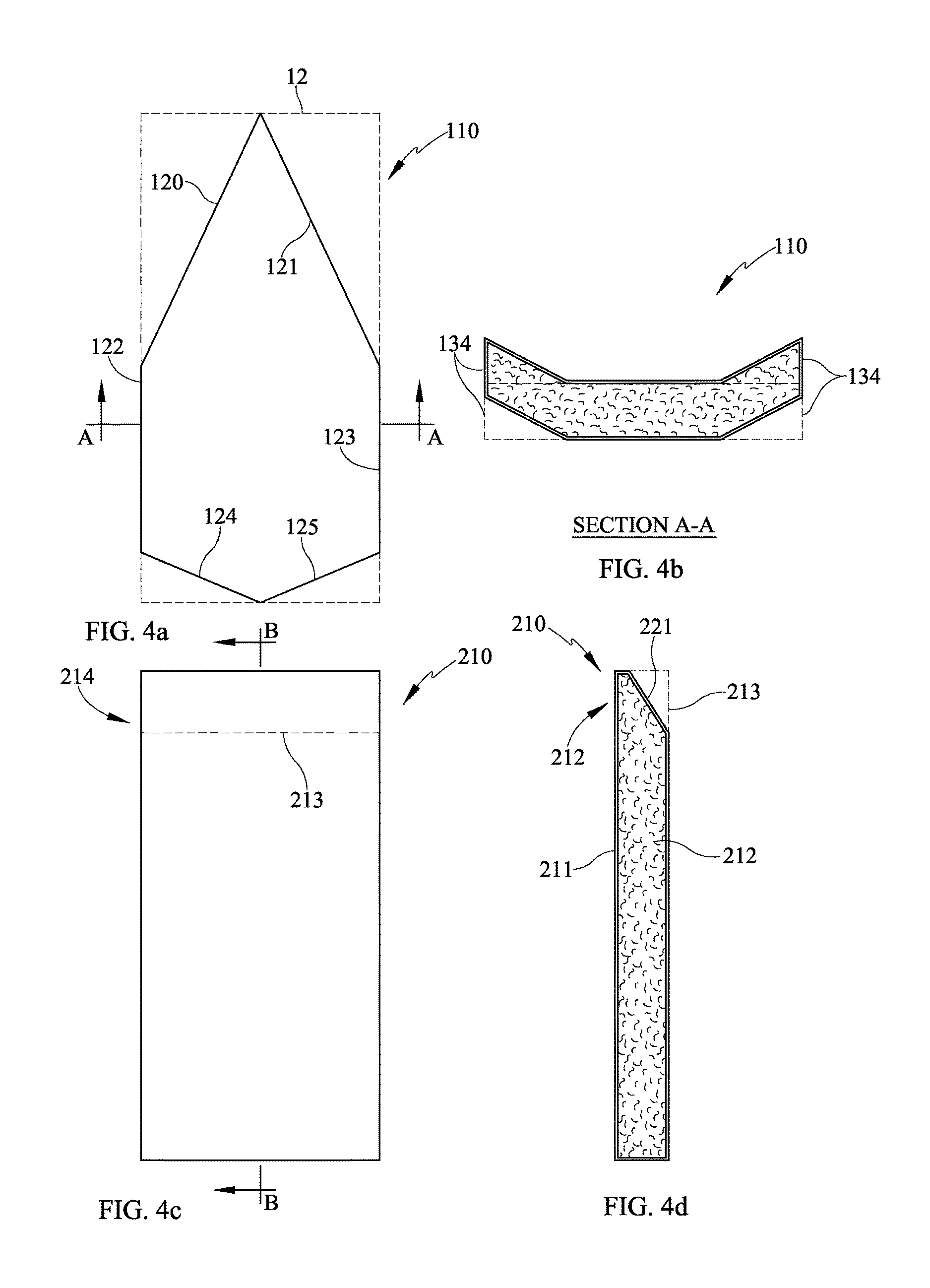
[0041]Referring now to FIG. 5c, a further alternative embodiment is depicted. In this embodiment, the hull 10 is again shown defined by a core material 12 covered on outer surfaces by a skin 11. The core 12 includes a hull hole 13 which is lined by a sleeve or insert 46. The hull hole 13 and sleeve 46 allow for passage of a rope, cable, zip-...


PUM

PropertyMeasurementUnit
sizesaaaaaaaaaa
sizesaaaaaaaaaa
sizesaaaaaaaaaa

Abstract

A boat hull or other marine structure is made by shaping a plastic foam core and covering it with a plastic outer skin glued in place by adhesive, mechanically fastened, or applied in liquid form. Minimal sawcuts to the foam core ease manufacture. Methods for anchoring fittings, masts, pipes and shade canopies are presented. No-sew sails for the boat have corners made of plastic sheet attached using both adhesive and mechanical fastening. Lateral resistance of the hull is provided by telescoping leeboards. A suite of these boats share the same modular masts and sails. Such boat hulls offer light weight, ease of transport, and unswampable buoyancy.

Description

CROSS-REFERENCE TO RELATED APPLICATIONS[0001]This Non-provisional application claims priority under 35 U.S.C. §119 (e) of U.S. Provisional Patent Application No. 61 / 870,095 filed Aug. 26, 2013, titled, “Lightweight Marinecraft and Methods Therefore”, all of which is incorporated herein by reference.BACKGROUND[0002]Field of the Invention[0003]Present embodiments relate to lightweight marine craft. More specifically, present embodiments generally relate to, without limitation, lightweight, low cost marine craft which may be modular to change design, size and capacity, as well as related methods therefore.[0004]Description of Related Art[0005]For almost 70 years, boat builders have used fiberglass fabric or fibers embedded in epoxy or polyester resin to make the hulls of boats, either formed in a mold, or laid up over a substrate structure such as a wood form or foam core. These molds and substrates, and the extensive labor required to apply and finish fiberglass, add to cost. While fi...

Claims


Application Information

Patent Timeline
Patent Type & Authority Patents(United States)
IPC IPC(8): B63B5/24B63B41/00B63H9/04B63B3/00B63B35/79B63B9/06
CPCB63B5/24B63H9/04B63B41/00B63B3/00B63B9/06B63B35/7906B63B73/46
Inventor ISAACS, MARK
Owner BETTA BOATS LLC
Why Eureka
Try Eureka