Infrared detection and imaging device with no moving parts

a technology which is applied in the field of infrared detection and imaging device, can solve the problems of cumbersome and expensive optical fabrication of exotic components, unsuitable for research projects, and not suitable for practical day-to-day civilian and industrial applications, and achieve the effect of reliable and low-cost devi

Active Publication Date: 2017-02-28
TECHNION RES & DEV FOUND LTD +1
View PDF3 Cites 2 Cited by
  • Summary
  • Abstract
  • Description
  • Claims
  • Application Information

AI Technical Summary

Benefits of technology

[0007]The present invention is a reliable and low cost device for detecting, imaging and quantifying an airborne gas in a specific range of concentration and cloud size. The device uses no moving parts and has an optical system based on a bistatic electronically controlled notch absorber, absorbing in the same wavelength range as the gas to be detected. The device alternately images a field of view through a bistatic absorber in the notch and out-of notch wavelength ranges, respectively.

Problems solved by technology

Such high end instrumentation provides large quantities of information, but is usually more suitable for research projects and not for practical day-to-day civilian and industrial applications, due to exceedingly high costs which may reach hundreds of thousands of dollars each.
Both are significant challenges: i) the former, because most hazardous gases in safety applications are transparent in the visible range and require more expensive infrared detectors, in order to be detected; ii) the latter, because the need for simultaneous spatial and spectroscopic information needed for detection and identification is more easily achieved with a spectral scanning method of some kind, usually requiring the movement of some optical component, such as a scanning mirror of an interferometer, a set of band pass filters mounted on a rotating wheel, or other.
Such snapshot methods still provide a spectral image with intermediate resolution in both wavelength and space parameters, but the optical fabrication of the required exotic components is cumbersome and expensive (such as reformatting coherent fiber bundles, lenslet arrays, and multiple mirror facets).

Method used


Image

  • Infrared detection and imaging device with no moving parts
  • Infrared detection and imaging device with no moving parts
  • Infrared detection and imaging device with no moving parts

Examples


Embodiment Construction

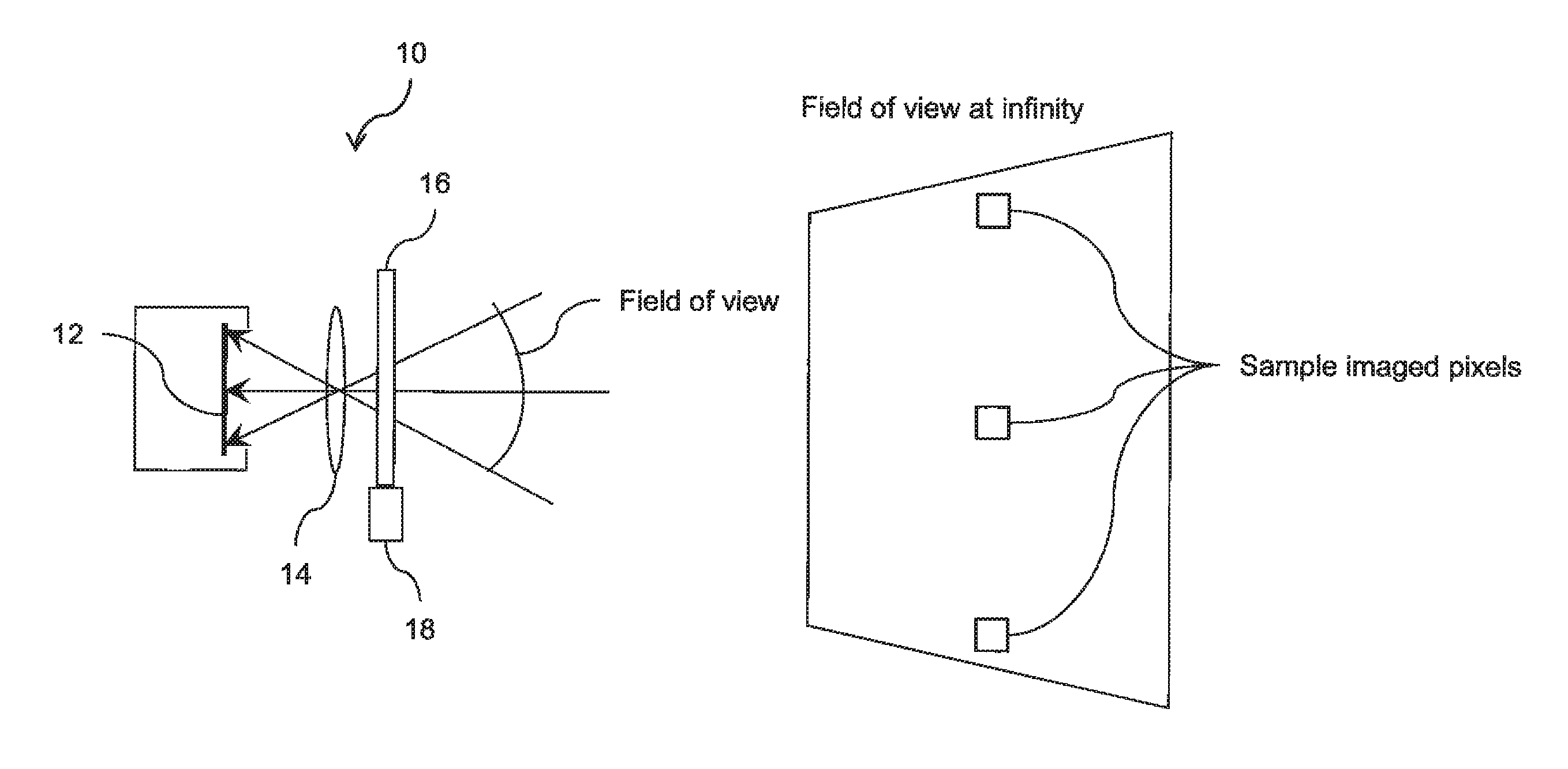
[0039]The principles and operation of the device according to the present invention may be better understood with reference to the drawings and the accompanying description.

[0040]Before explaining at least one embodiment of the invention in detail, it is to be understood that the invention is not necessarily limited in its application to the details of construction and the arrangement of the components and / or methods set forth in the following description and / or illustrated in the drawings and / or the examples. The invention is capable of other embodiments or of being practiced or carried out in various ways. Initially, throughout this document, references are made to directions such as, for example, right, left, and the like. These directional references are exemplary only to illustrate the invention and embodiments thereof.

[0041]The present disclosure is of a device for detecting and imaging a specific gas in the air in a specific range of concentration and cloud size that may be a...


PUM

PropertyMeasurementUnit
wavelength rangeaaaaaaaaaa
transmittanceaaaaaaaaaa

Abstract

A device images radiation from a scene. A detector is sensitive to the radiation in a first wavelength band. A lens forms an image of the scene on the detector. A filtering arrangement includes two sets of radiation absorbing molecules. A control unit switches the filtering arrangement between two states. In the first state, all of the radiation in the first wavelength band is transmitted to the detector. In the second state, the radiation in a second wavelength band within the first wavelength band is absorbed by the radiation absorbing molecules. The control unit synchronizes the switching of the filtering arrangement with the detector. Each pixel of the image formed on the detector includes two signals. The first signal includes information from the scene radiation in the first wavelength band. The second signal excludes information from the scene radiation absorbed by the filtering arrangement in the second wavelength band.

Description

CROSS-REFERENCE TO RELATED APPLICATIONS[0001]This application claims priority from U.S. Provisional Patent Application No. 62 / 077,328, filed Nov. 10, 2014, whose disclosure is incorporated herein by reference.TECHNICAL FIELD[0002]The present invention relates to the detection and imaging of infrared radiation.BACKGROUND OF THE INVENTION[0003]The last twenty five years have seen a very large amount of work done in the field of multispectral and spectral imaging all around the world, in industry and academia. The motivation is to collect spatially and spectrally resolved radiance information of a predefined region of space. The number and fields of application of such information are innumerable; as a result, the different optical configurations used in the design of instrumentation built for this purpose have also been innumerable, in order to provide the needed information through a method and format most suitable for the relevant application. Instrumentation has been built for labo...

Claims


Application Information

Patent Timeline
Patent Type & Authority Patents(United States)
IPC IPC(8): G01N21/3504G01N21/31
CPCG01N21/3504G01N21/314G01N2021/3531G01N2021/317G02F1/137H04N5/33
Inventor CABIB, DARIOGIL, AMIRROTSCHILD, CARMELWOLOWELSKY, KARNI
Owner TECHNION RES & DEV FOUND LTD
Why Eureka
Try Eureka