Tool for torsion bar repair

a torsion bar and tool technology, applied in the field of tools, can solve the problems of affecting the use so as to enhance the versatility of the subject invention, prevent slippage, and facilitate the use and applicability.

a torsion bar and tool technology, applied in the field of tools, can solve the problems of affecting the use so as to enhance the versatility of the subject invention, prevent slippage, and facilitate the use and applicability.

US9597778B2Active Publication Date: 2017-03-21VERBOWSKI LARRY JOHN

Image

  • Tool for torsion bar repair
  • Tool for torsion bar repair
  • Tool for torsion bar repair

Examples


Embodiment Construction

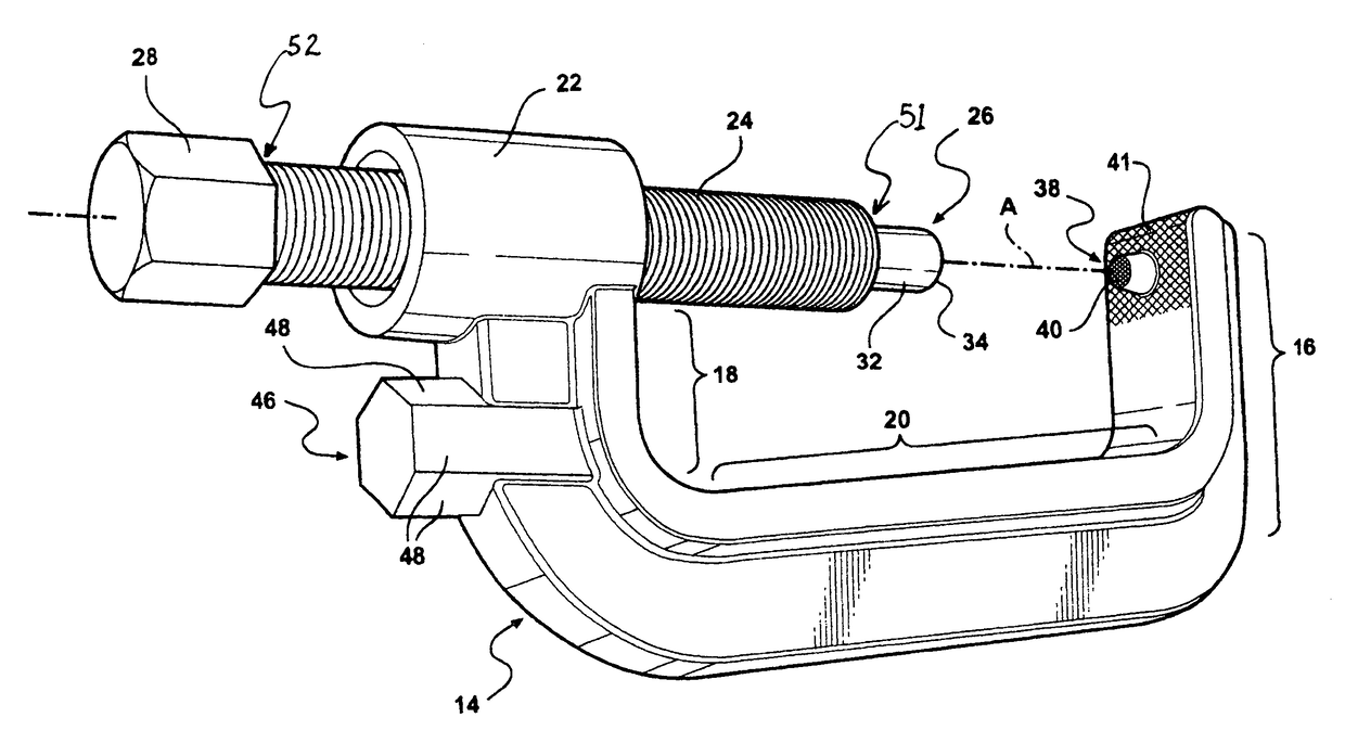
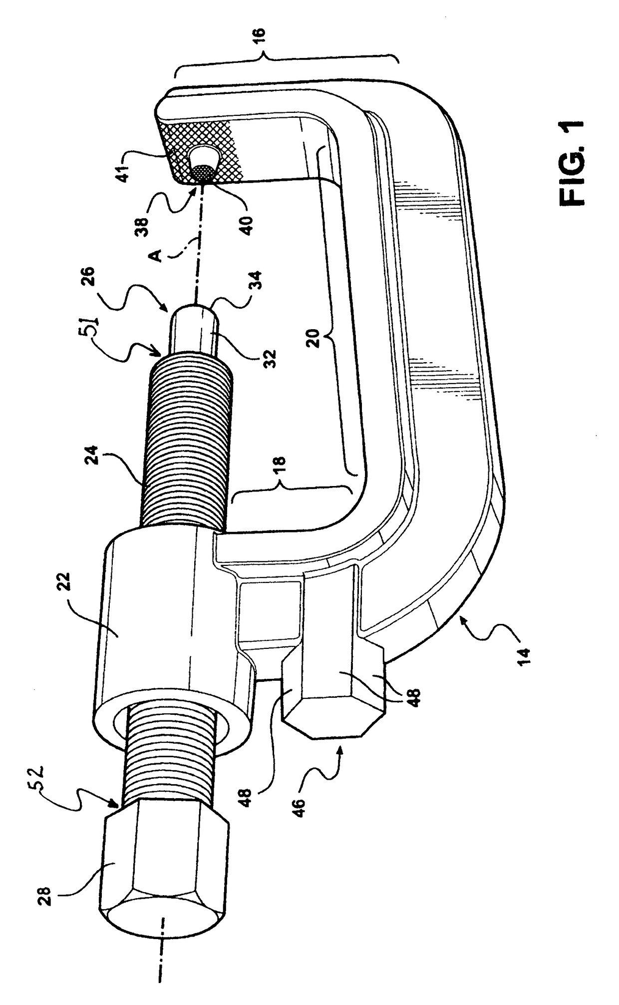
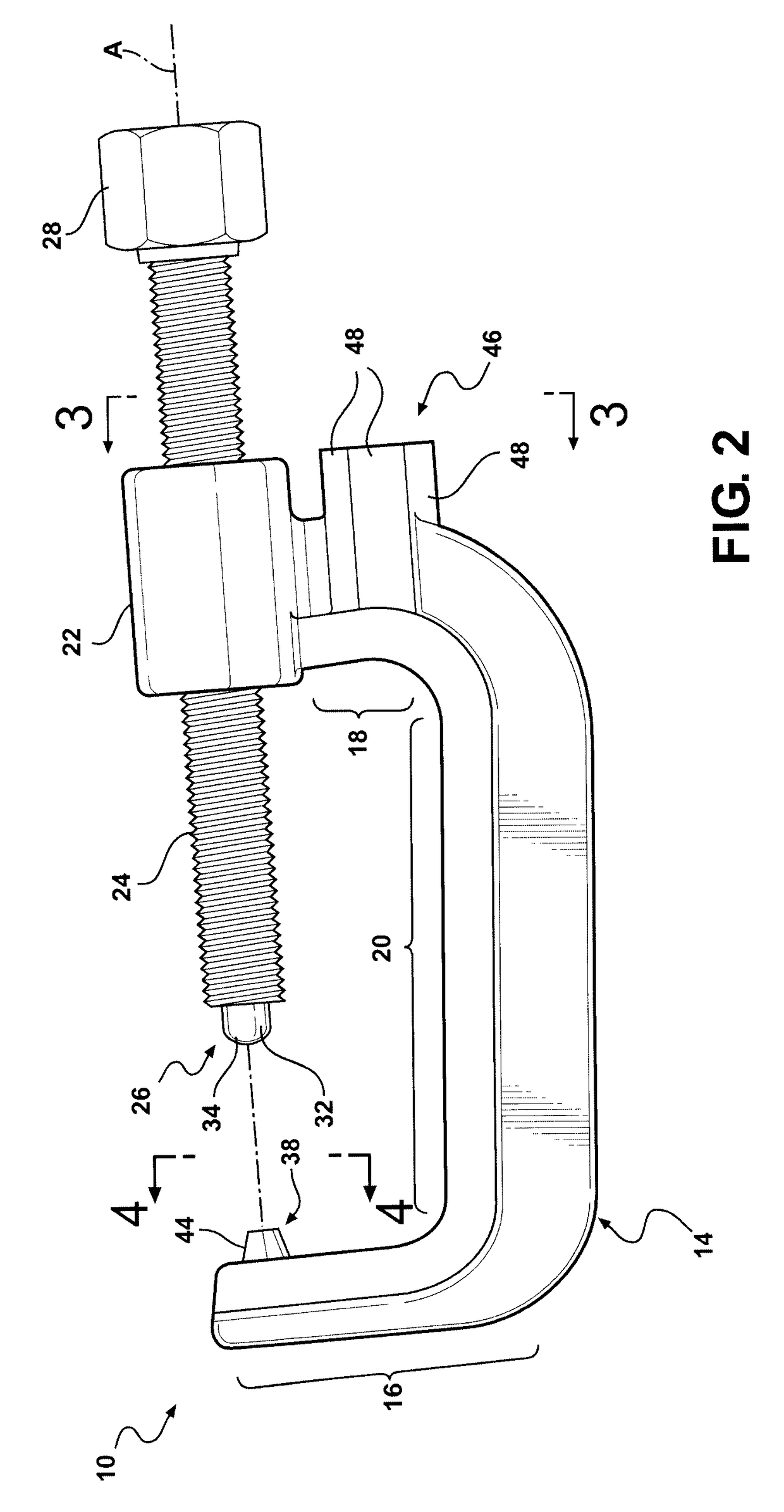
[0025]Referring to the Figures, wherein like numerals indicate like or corresponding parts throughout the several views, an unloader tool assembly according to the subject invention is generally shown at 10. The tool assembly 10 is of the type for removing an adjusting member in a torsion bar 11 suspension system for a motor vehicle. The adjusting member can be a cam, wedge, ratchet or other mechanical or electromechanical device, but in the most common applications comprises an adjusting bolt 12 as depicted in FIGS. 7 and 8. The adjusting bolt 12 is threaded through a cross-nut 13. The tool assembly 10 includes a tool body, generally indicated at 14, having an upper section 16, a lower section 18, and a riser section 20 interconnecting the upper 16 and lower 18 sections. In cross-section, each of the sections 16, 18, 20 are shown having a generally T-shaped configuration designed for maximum rigidity. Preferably, these sections 16-20 are arranged end-to-end into a generally C-shape...


PUM


Abstract

A method and tool assembly (10) for unloading and reloading spring energy from a torsion bar (11) in a torsion bar suspension system of a motor vehicle. The tool assembly (10) includes a generally C-shaped body (14) having a screw shaft (24) threaded through a boss (22) in a lower section (18) thereof. An anti-rotation stem (38) includes a knurled flat face (40) which increases versatility of the tool assembly (10) by enabling anti-slip operation with various vehicle types. A counter-torque tool perch (46) extends from the lower section (18) of the tool body (14) for applying a counter-rotational torque to the body (14) during use of the tool assembly (10).

Description

CROSS REFERENCE TO RELATED APPLICATIONS[0001]This application claims priority to U.S. Provisional Patent Application No. 61 / 026,493 which was filed on Feb. 6, 2008, the entire disclosure of which is hereby incorporated by reference and relied upon.BACKGROUND OF THE INVENTION[0002]Field of the Invention[0003]This invention relates generally to a tool of the type used to service a torsion bar suspension system in a motor vehicle, and more particularly toward an unloading tool used to remove and restore spring energy in a torsion bar suspension system.[0004]Related Art[0005]Some motor vehicle suspensions use a torsion bar as a weight bearing spring. In this arrangement, one end of a long, usually metal torsion bar is attached firmly to the vehicle chassis and its opposite end is attached to an unsprung suspension component such as a suspension arm, spindle, axle or the like. Vertical motion of the vehicle wheel causes the torsion bar to twist which is resisted by the torsion bar's inhe...

Claims


Application Information

Patent Timeline
21 Mar 2017
Publication
US9597778B2
IPC
B25B5/10; B25B27/30
CPC
B25B5/101; B25B27/30; B60G2206/93
Inventors
VERBOWSKI, LARRY JOHN