Inverter-integrated electric compressor and assembly method therefor

a technology of electric compressor and integrated circuit, which is applied in the direction of positive displacement liquid engine, piston pump, liquid fuel engine, etc., can solve the problems of lead terminal deformation or breakage with long-term use, poor workability of assembling inverter and its surrounding area, and complex assembly procedure. achieve satisfactory workability and effective dissipation of heat-generating electrical components

Active Publication Date: 2017-03-21
MITSUBISHI HEAVY IND LTD
View PDF28 Cites 11 Cited by
  • Summary
  • Abstract
  • Description
  • Claims
  • Application Information

AI Technical Summary

Benefits of technology

[0015]In view of these circumstances, an object of the present invention is to provide an inverter-integrated electric compressor that can effectively dissipate the heat of a heat-generating electrical component mounted on a control circuit board of an inverter, prevent a lead terminal that connects this electrical component to the control circuit board from breaking due to vibration, and provide satisfactory workability for assembling the inverter and its surrounding area, as well as providing an assembly method therefor.

Problems solved by technology

As a result, metal fatigue accumulates in lead terminals (pin terminals) that connect the electrical components to the control circuit board, possibly leading to deformation or breakage of the lead terminals with long-term use.
Therefore, an assembly procedure that involves a difficult and complicated positioning process is necessary, and moreover, the soldering process needs to be performed within the inverter box of the electric compressor.
For this reason, the main body of the electric compressor needs to be conveyed in the assembly line of the inverter, resulting in extremely poor workability for assembling the inverter and its surrounding area.

Method used


Image

  • Inverter-integrated electric compressor and assembly method therefor
  • Inverter-integrated electric compressor and assembly method therefor
  • Inverter-integrated electric compressor and assembly method therefor

Examples


first embodiment

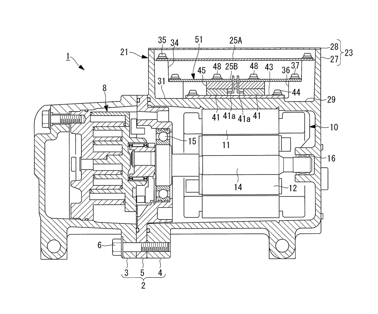
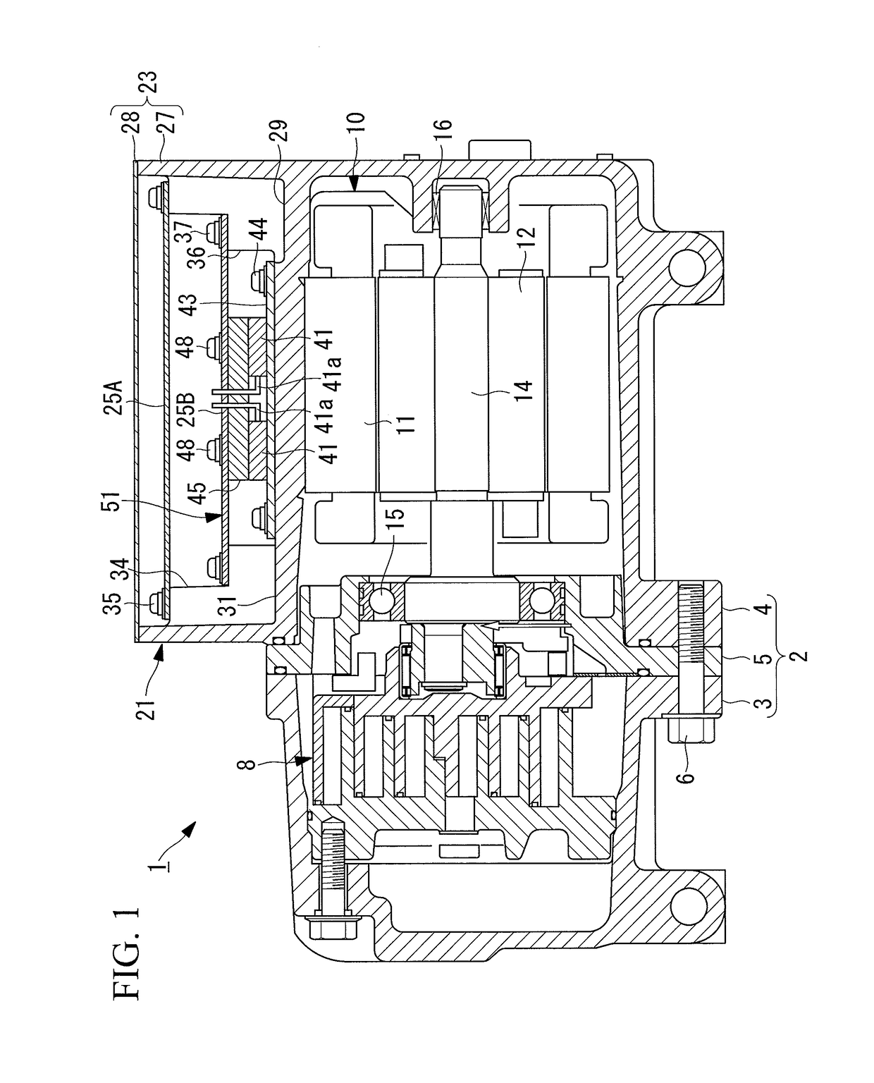
[0039]A first embodiment of the present invention will be described below with reference to FIGS. 1 to 3. FIG. 1 is a vertical sectional view for explaining the schematic configuration of an inverter-integrated electric compressor according to this embodiment. An inverter-integrated electric compressor 1 is a compressor used in a vehicle air conditioner, and the driving rotation speed thereof is controlled by an inverter.

[0040]The inverter-integrated electric compressor 1 has an aluminum-alloy housing 2 serving as an outer shell. The housing 2 is constituted of a compressor housing 3 and a motor housing 4 that are tightly fastened to each other with a bearing housing 5 interposed therebetween by using a bolt 6.

[0041]A commonly known scroll compression mechanism 8 is fitted within the compressor housing 3. A stator 11 and a rotor 12 that constitute a motor 10 are fitted within the motor housing 4. The scroll compression mechanism 8 and the motor 10 are linked with each other via a ma...

second embodiment

[0060]Next, a second embodiment of the present invention will be described with reference to FIG. 4 and FIGS. 5A to 5C.

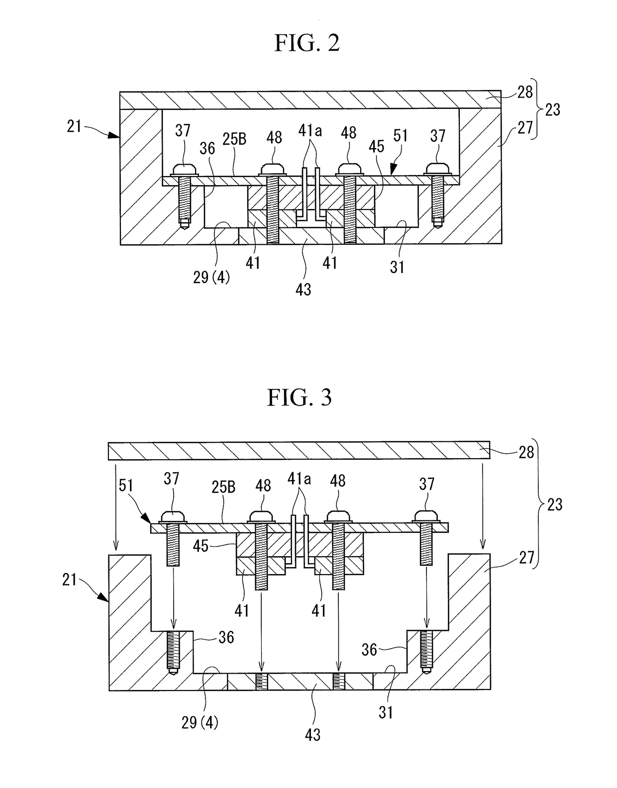
[0061]In FIG. 4 and FIGS. 5A to 5C, components that are the same as those in the first embodiment shown in FIGS. 1 to 3 are given the same reference numerals, and descriptions thereof will be omitted.

[0062]In the second embodiment, bonding layers 62 are formed on both upper and lower surfaces of a spacer member 61. The bonding layers 62 function as bonding members for bonding the spacer member 61 to the lower board 25B and the IGBTs 41, and can conceivably be composed of an adhesive material, such as an adhesive or double-sided tape, or a heat-weldable joining material, such as solder layers or adhesive resin layers. Although only one bonding layer 62 may be provided on one of the upper and lower surfaces of the spacer member 61, it is preferable that both the upper and lower surfaces be provided with bonding layers 62.

[0063]Unlike the first embodiment, the IGBTs 41...

third embodiment

[0069]Next, a third embodiment of the present invention will be described with reference to FIG. 6.

[0070]In FIG. 6, components that are the same as those in the second embodiment shown in FIG. 4 are given the same reference numerals, and descriptions thereof will be omitted.

[0071]In the third embodiment, the IGBTs 41 are fastened to the heat conducting member 43 using screws 71. Furthermore, recesses 73 for accommodating the heads of the screws 71 are formed in the lower surface of a spacer member 72. Bonding layers 62 similar to those in the second embodiment are used for bonding and positioning between the IGBTs 41 and the spacer member 72 and between the spacer member 72 and the lower board 25B.

[0072]With this configuration, the IGBTs 41 alone are first fastened to the heat conducting member 43 using the screws 71, thereby ensuring reliable heat dissipation. The recesses 73 in the lower surface of the spacer member 72 may alternatively be through-holes extending through the space...


PUM

PropertyMeasurementUnit
elasticaaaaaaaaaa
rotation speedaaaaaaaaaa
thicknessaaaaaaaaaa

Abstract

An IGBT serving as a heat-generating electrical component mounted on the lower surface of a lower board serving as a control circuit board of an inverter is disposed in abutment with a heat-dissipating flat section provided on an inner wall of an inverter box provided on the outer periphery of a housing so that the heat of the IGBT is dissipated toward the housing. Moreover, a spacer member is interposed between the lower board and the IGBT so as to fill a space between the lower board and the IGBT, and the spacer member is rigid enough that the lower board and the IGBT are prevented from being displaced toward and away from each other.

Description

BACKGROUND OF THE INVENTION[0001]1. Field of the Invention[0002]The present invention relates to an inverter-integrated electric compressor particularly suitable for use in a vehicle air conditioner and formed by installing an inverter inside an inverter box provided on the outer periphery of a housing, and to an assembly method therefor.[0003]This application is based on Japanese Patent Application No. 2010-027733, the content of which is incorporated herein by reference.[0004]2. Description of Related Art[0005]In recent years, in addition to vehicles that run using internal combustion engines, vehicles that run by utilizing electric power, such as electric vehicles, hybrid vehicles, and fuel-cell-powered vehicles, are rapidly being developed and made commercially available. In many air conditioners for such vehicles that utilize electric power, electric compressors having motors that operate with electric power as a driving source are used as compressors for compressing and supply...

Claims


Application Information

Patent Timeline
Patent Type & Authority Patents(United States)
IPC IPC(8): F04C18/02F04B39/06F04B35/04F04C29/04F04B39/12
CPCF04C18/0215F04B39/06F04B39/121F04C29/047F04B35/04F04C18/0223Y10T29/49002
Inventor YAKUSHIJI, SHUNSUKE
Owner MITSUBISHI HEAVY IND LTD
Why Eureka
Try Eureka