
Method and device for active control of mechanical vibrations by implementation of a control law consisting of a central corrector and a Youla parameter

a technology of mechanical vibration and control law, which is applied in the direction of adaptive control, computer control, instruments, etc., can solve the problems of limitation of the isolation produced by these pads, which are often made of elastomers, and machines always produce vibrations, so as to reduce vibration intensity and reduce vibration.

Active Publication Date: 2017-03-21
EXAIL
View PDF6 Cites 0 Cited by
  • Summary
  • Abstract
  • Description
  • Claims
  • Application Information

AI Technical Summary

Benefits of technology

This patent proposes a method to reduce vibrations caused by a rotating machine in an active engine-physical structure vibratory isolation system. An actuator is installed to counteract the vibrations, which can be placed in series or parallel with the support structure. The actuator can be electromechanical or fluid-based, and a sensor is used to measure the vibrations before the active corrector is applied. The purpose is to reduce the intensity and impact of vibrations on the physical structure.

Problems solved by technology

Such machines always produce vibrations that are transmitted to the physical structures to which they are fixed through fixation supports connecting the rotary machine to its physical structure.
Such vibrations are often caused by the unbalance of the rotary axis, i.e. an out-of-balance defect of the rotary axis.
Nevertheless, for reasons of fixation strength, it is not possible to make these pads very supple, and thus very damping, which necessarily causes a limitation of the isolation produced by these pads often made of elastomer.

Method used


Image

  • Method and device for active control of mechanical vibrations by implementation of a control law consisting of a central corrector and a Youla parameter
  • Method and device for active control of mechanical vibrations by implementation of a control law consisting of a central corrector and a Youla parameter
  • Method and device for active control of mechanical vibrations by implementation of a control law consisting of a central corrector and a Youla parameter

Examples


Embodiment Construction

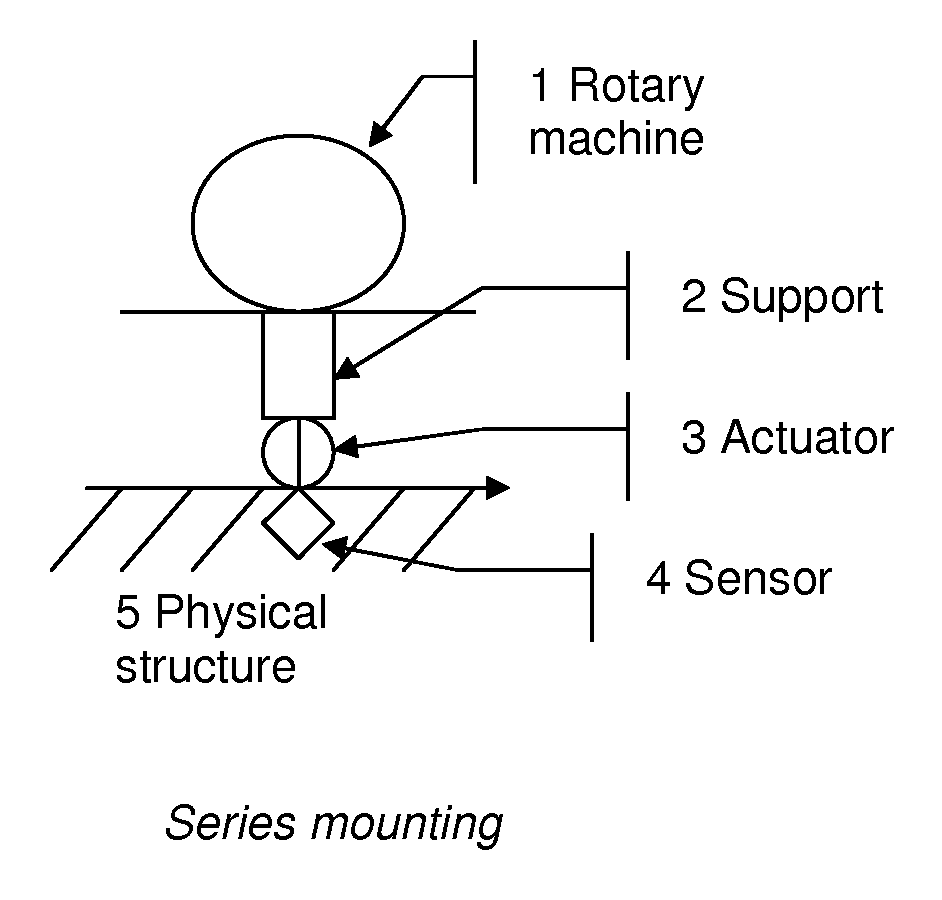
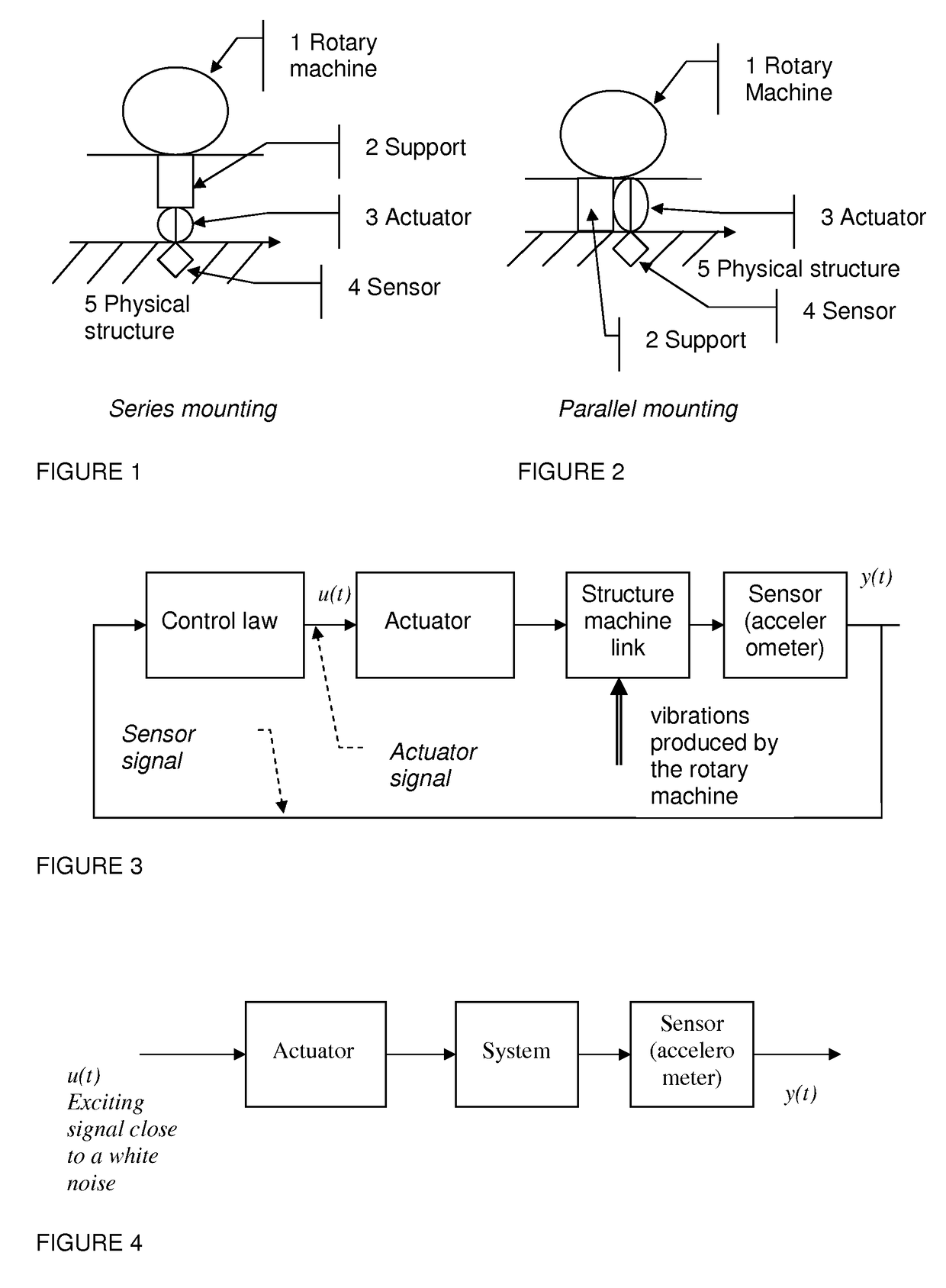
[0097]In the following, a device for active control of vibrations for active isolation of rotary machines is presented. The rotary machine 1 is connected to a physical structure 5 by means of one or several fixation supports 2 including or not vibration mechanical damping means of the “Silentbloc” type or other. The device is consisted of at least one sensor 4 and one or several actuators 3 integrated in the rotary machine support(s), cf. series mounting in FIG. 1, or in parallel with the rotary machine support(s), cf. parallel mounting in FIG. 2.

[0098]In FIGS. 1 and 2, the diagram is simplified with only one actuator and only one sensor for the single support shown. In practice, the rotary machine may be connected to the physical structure by several supports and each support may include one or several actuators. Preferably, it is implemented one sensor per support, sensor that is on the physical structure but in direct relation with the support, for example on the means for fixing...


PUM


Abstract

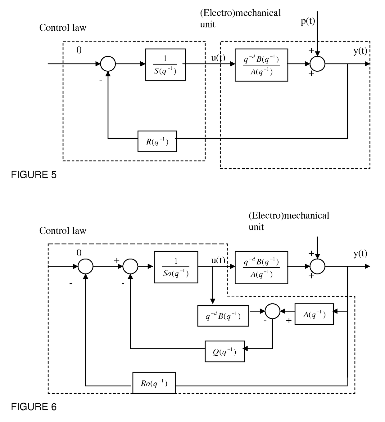
A method and a device are based on the application of an active correcting system with central corrector and Youla parameter for the attenuation of essentially monofrequency mechanical vibratory perturbations generated in a material structure by a rotating machine. Previously, a control law corresponding to a block modeling of the system is established and calculated, the blocks being, on the other hand, those of the central corrector and, on the other hand, a Youla parameter block, the modeling being such that only the Youla parameter, in the form of an infinite impulse response filter, has coefficients dependent on the vibratory perturbation frequency. During a phase of use, in real time, the frequency of the current perturbation is determined and the control law is calculated using for the Youla parameter the stored coefficients of a determined perturbation frequency corresponding to the current perturbation frequency.

Description

BACKGROUND OF THE INVENTION[0001]Field of the Invention[0002]The present invention relates to a method and a device for active control of mechanical vibrations by implementation of a control law consisted of a central corrector and a Youla parameter.[0003]Description of the Related Art[0004]There exist many industrial cases of use of rotary machines. Such machines always produce vibrations that are transmitted to the physical structures to which they are fixed through fixation supports connecting the rotary machine to its physical structure. The rotary character of the above-mentioned machines leads in that the spectrum of the transmitted vibrations has peaks at frequencies proportional to the speed of rotation of the rotary axis. Such vibrations are often caused by the unbalance of the rotary axis, i.e. an out-of-balance defect of the rotary axis. In the frequency domain, the peaks observed in the spectrum of the transmitted vibrations have frequencies in Hertz that are equal to th...

Claims


Application Information

Patent Timeline
IPC IPC(8): G05D19/02G05B13/02F16F15/00
CPCG05D19/02F16F15/002G05B13/025
Inventor VAU, BERNARD
Owner EXAIL
Learn More