Wireless communications terminal, base station device, and resource allocation method

a technology of wireless communication and base station devices, applied in the direction of wireless communication, transmission path sub-channel allocation, digital transmission, etc., can solve problems such as retransmission of data, achieve the effect of avoiding collision between a/n signals, avoiding unnecessary reduction of pusch bands, and increasing a/n resource utilization efficiency

Active Publication Date: 2017-03-21
SUN PATENT TRUST
View PDF9 Cites 8 Cited by
  • Summary
  • Abstract
  • Description
  • Claims
  • Application Information

AI Technical Summary

Benefits of technology

[0033]According to the present invention, in the case where control information is transmitted on the enhanced physical downlink control channel and the physical downlink control channel, it is possible to increase the A / N resource utilization efficiency and to avoid an unnecessary reduction of the PUSCH band while avoiding collision between A / N signals for downlink data.

Problems solved by technology

If, however, the decoding fails, the terminal feeds back a NACK to the base station, prompting retransmission of the data in which an error is detected.

Method used


Image

  • Wireless communications terminal, base station device, and resource allocation method
  • Wireless communications terminal, base station device, and resource allocation method
  • Wireless communications terminal, base station device, and resource allocation method

Examples


embodiment 1

Background of Obtaining an Embodiment of the Present Invention

[0055]First, before describing the specific configuration and operation of Embodiment 1, one method that the inventors of the present invention have noticed as a method for allocating A / N resources in the case of adopting the E-PDCCH will be described.

[0056]FIG. 4 shows an example of the downlink subframe at the time of E-PDCCH transmission. FIG. 5 shows the system configuration when E-PDCCH is adopted.

[0057]As shown in FIG. 5, in a communication system adopting the E-PDCCH, it is expected that PDCCH terminals and E-PDCCH terminals are mixed within one cell (the E-PDCCH terminals in FIG. 5 being shown in black). In this case, a PDCCH terminal is a terminal that receives PDCCH control information for controlling its communication, and an E-PDCCH terminal is a terminal that receives E-PDCCH control information for controlling its communication.

[0058]The E-PDCCH has the following features.

[0059](1) Unlike the PDCCH, which is...

embodiment 2

Background of Obtaining an Embodiment of the Present Invention

[0177]First, before describing the specific configuration and operation of Embodiment 2, one method that the inventors noticed as a method for allocating A / N resources in the case of adopting the E-PDCCH will be described.

[0178]The CoMP scenario 4 is operation that is expected to increase the number of terminals in the coverage area, using E-PDCCH. FIG. 14 shows an example of the configuration of a communication system adopting CoMP scenario 4. First, at this point an example in which no E-PDCCH is used is shown. A plurality of pico nodes are placed within a cell of a macro base station that forms a large cell (in CoMP scenario 4, a macro base station being hereafter called a macro node and a pico base station being hereafter called a pico node). In CoMP scenario 4, these nodes are operated by a single cell ID. In this CoMP scenario 4, because cooperative transmission on the downlink and cooperative reception on the uplin...


PUM


Abstract

The purpose of the present invention is to avoid ACK / NACK collision in a system in which E-PDCCH control information is transmitted, increase the utilization efficiency of ACK / NACK resources, and suppress unnecessary PUSCH band reduction. A wireless communications terminal having a configuration comprising: a reception unit that receives control signals including ACK / NACK indexes, via an expanded physical downlink control channel; a control unit that determines, on the basis of the ACK / NACK indexes, whether to use a dynamically allocated dynamic ACK / NACK resource or a specified resource specified beforehand, to send downlink data ACK / NACK signals; and a transmission unit that sends the ACK / NACK signals using the dynamic ACK / NACK resource or the specified resource, as determined.

Description

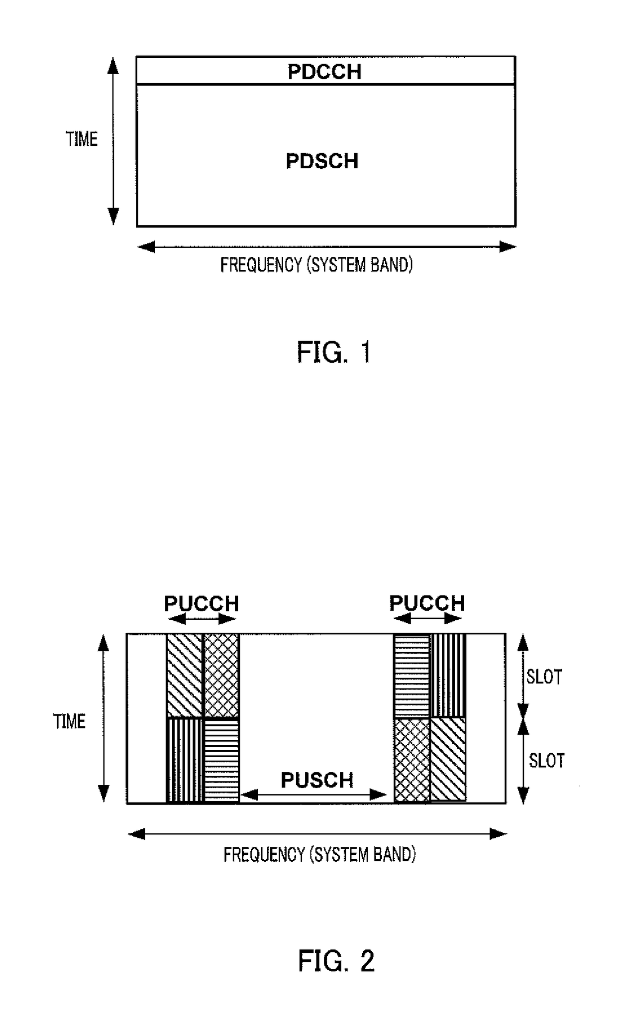
TECHNICAL FIELD[0001]The present invention relates to a radio communication terminal, a base station apparatus, and an ACK / NACK signal resource allocation method.BACKGROUND ART[0002]The 3GPP (3rd Generation Partnership Project Radio Access Network) has established LTE (Long Term Evolution) Rel. 8 (Release 8) and the extended version of LTE, which is LTE Rel. 10 (LTE-Advanced). In these standards, a base station, and a radio communication terminal (also called “UE (User Equipment)” and referred to below as a terminal) transmit control information for transmitting and receiving data using a downlink PDCCH (physical downlink control channel) (refer to Non-Patent Literature 1 to 3). FIG. 1 shows the subframe configuration of the downlink. In the subframes, the PDCCH that transmits a control signal and the PDSCH (physical downlink shared channel) that transmits a data signal are time-division multiplexed. The terminal first decodes the control information transmitted to the terminal thro...

Claims


Application Information

Patent Timeline
Patent Type & Authority Patents(United States)
IPC IPC(8): H04L1/18H04W72/04H04L1/00
CPCH04L1/1854H04L1/0038H04L1/1864H04W72/042H04L5/0055H04W72/23
Inventor TAKEDA, KAZUKIOIZUMI, TORUHORIUCHI, AYAKONISHIO, AKIHIKO
Owner SUN PATENT TRUST
Why Eureka
Try Eureka