Exhaust passage

a technology of exhaust passage and exhaust pipe, which is applied in the direction of engines, mechanical equipment, machines/engines, etc., can solve the problems of adding to the weight and cost of the two-mixer system, requiring separate fabrication of the element of the twist mixer, and the welding intensity of the traditional twist mixer, so as to reduce the weight and cost of the system, reduce the manufacturing cost, and achieve good atomization and mixing

Active Publication Date: 2017-03-28
FORD GLOBAL TECH LLC
View PDF38 Cites 2 Cited by
  • Summary
  • Abstract
  • Description
  • Claims
  • Application Information

AI Technical Summary

Benefits of technology

[0005]Accordingly, in one example, some of the above issues may be addressed by an exhaust passage comprising an exterior wall having an inwardly-protruding indentation traversing at least once around the exhaust passage in a helical path. The exterior wall then defines an interior passage configured to receive engine exhaust gas and direct the engine exhaust gas via the inwardly-protruding indentation. In this way, by having the indentation structure configured within the wall of the passage, separate elements traditionally welded into mixing devices may be eliminated, such as a mixing element, center rod, and stiffener bar, if desired. The exhaust passage may further include an atomizer of a partial disc shape positioned in the exhaust passage upstream of the portion comprising the inwardly-protruding indentation, which is configured to redirect exhaust flow and catch a fluid spray for atomization. The partial disc shape eliminates the overall circular design (e.g., with a circular perimeter) of traditional atomizers, and may utilize fewer louvers than traditional atomizers, thus reducing the weight and cost of the system. As such, the exhaust passage can achieve good atomization and mixing, at a lower manufacturing cost.

Problems solved by technology

First, the atomizer is typically stamped and processed as a round element to fit into the exhaust system, and the numerous louvers add to the weight and cost of the two-mixer system.
Second, the mixing element of the twist mixer typically requires separate fabrication.
Further, traditional twist mixers may be welding-intensive, in that the center rod and a stiffener bar are welded at the outlet, and the whole assembly is then welded to a conical shell.

Method used


Image

  • Exhaust passage
  • Exhaust passage
  • Exhaust passage

Examples


Embodiment Construction

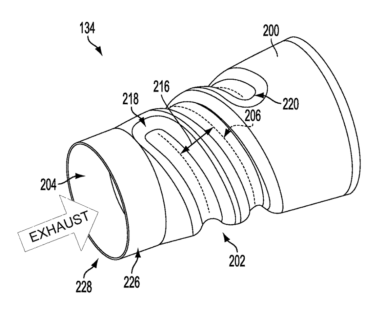
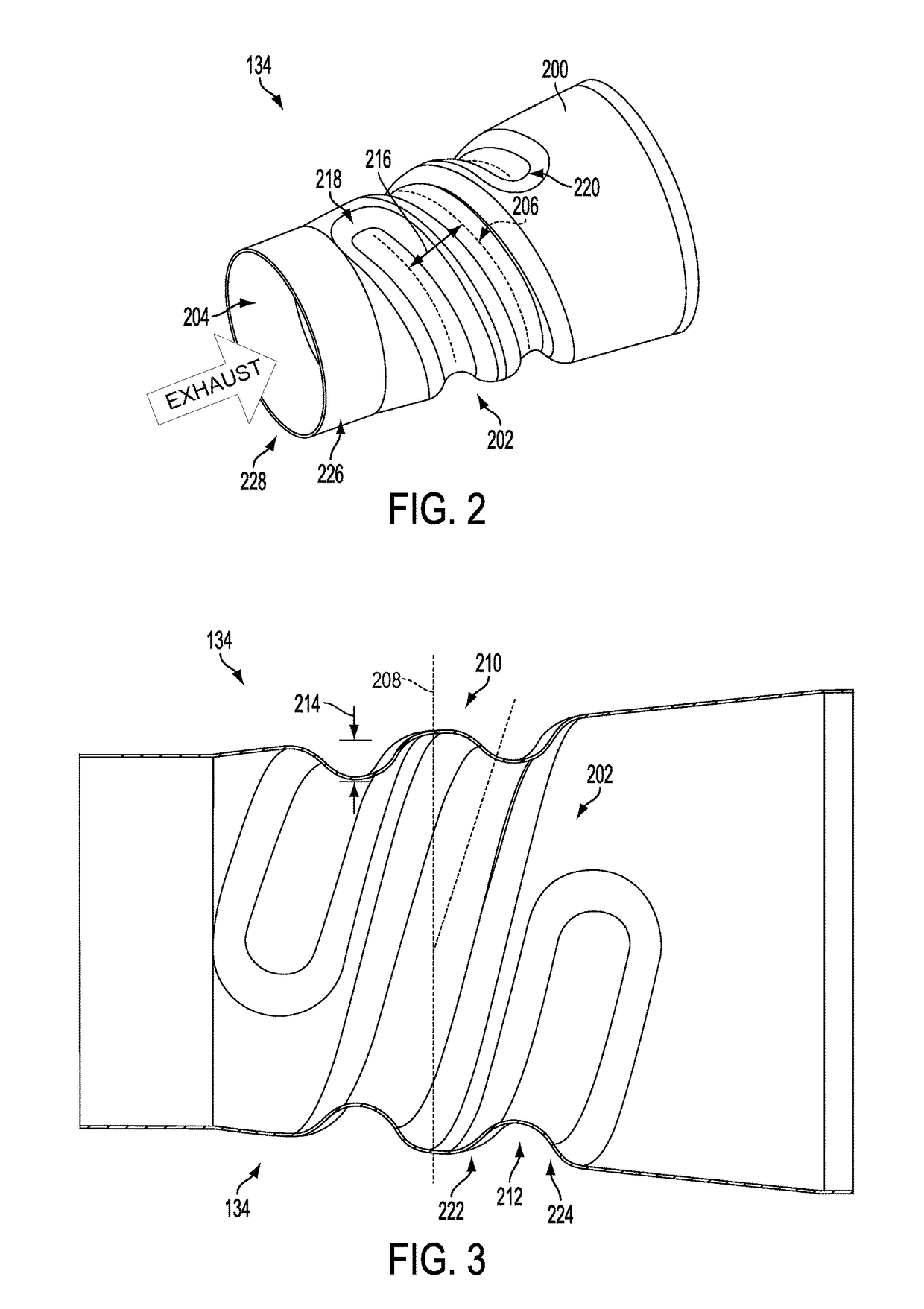
[0012]Embodiments of an exhaust passage are disclosed herein. Such an exhaust passage may be utilized for NOx reduction in an exhaust stream, as described in more detail hereafter. Various of the figures are drawn approximately to scale, including FIGS. 2-5.

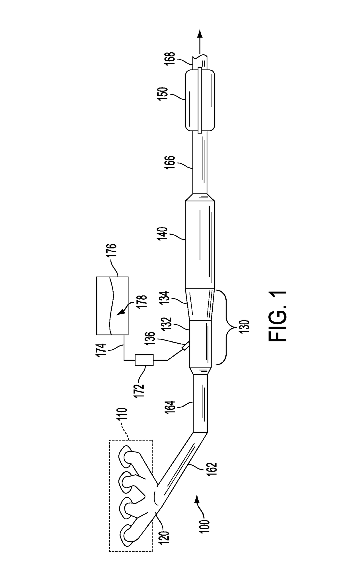
[0013]FIG. 1 illustrates an exhaust system 100 for transporting exhaust gases produced by internal combustion engine 110. As one non-limiting example, engine 110 includes a diesel engine that produces a mechanical output by combusting a mixture of air and diesel fuel. Alternatively, engine 110 may include other types of engines such as gasoline burning engines, among others.

[0014]Exhaust system 100 may include one or more of the following: an exhaust manifold 120 for receiving exhaust gases produced by one or more cylinders of engine 110, a mixing region 130 arranged downstream of exhaust manifold 120 for receiving a liquid reductant, a selective catalytic reductant (SCR) catalyst 140 arranged downstream of the mixing region 130,...


PUM


Abstract

An exhaust system comprises a conical shell having an indentation traversing the exhaust passage in a coiled path so as to impart mixing on an engine exhaust gas flowing through an inner passage defined by the conical shell. The indentation may be formed into the conical shell via a stamping process.

Description

TECHNICAL FIELD[0001]The present application relates to an exhaust system.BACKGROUND AND SUMMARY[0002]A technology such as Selective Catalyst Reduction (SCR) may be utilized for NOx reduction and to achieve diesel emissions requirements. In one approach, aqueous urea is sprayed into the exhaust gas stream which subsequently reacts with NOx on the surface of an SCR catalyst, resulting in reduction of engine-out NOx emissions. For improved NOx reduction under some conditions, the liquid urea sprayed into the diesel exhaust is typically atomized and mixed before it reaches the catalyst substrate.[0003]In one mixing approach, a two-mixer system may be utilized to provide such mixing, where a first element (e.g., an atomizer) of the system redirects the exhaust flow and catches the urea spray for atomization, and a second element (e.g., a twist mixer) aids in mixing the exhaust flow. As an example, the atomizer may include several (e.g., nine) louvers, and the twist mixer may include a h...

Claims


Application Information

Patent Timeline
Patent Type & Authority Patents(United States)
IPC IPC(8): F01N3/00F01N3/28F01N13/18
CPCF01N3/2892F01N13/1872F01N2240/20F01N2470/06F01N2470/12
Inventor NAVATHE, SUDHAKARROBERTS, JOHNBELTRAMO, JOEL JOHN
Owner FORD GLOBAL TECH LLC
Why Eureka
Try Eureka