Inductive sensor for a position measuring system, method of manufacturing inductive sensor, and position measuring system provided with inductive sensor

a technology of inductive sensor and position measuring system, which is applied in the direction of magnets, magnets, instruments, etc., can solve the problems of unsuitability of plastic covers, etc., and achieve the effect of simplifying the manufacturing of sensors

Active Publication Date: 2017-03-28
ROBERT BOSCH GMBH
View PDF34 Cites 1 Cited by
  • Summary
  • Abstract
  • Description
  • Claims
  • Application Information

AI Technical Summary

Benefits of technology

[0008]The object of the present invention is to create a sensor of the type generically defined in the preamble in which it is possible to select a smaller distance between the conducting coils and the associated material measure. In addition, the manufacture of the sensor should be simplified.
[0009]This object is attained in that the metal plate for covering is simultaneously used as a substrate that gives the conducting coil the necessary stability. It is therefore possible to eliminate the separate substrate. It is also possible to apply the conducting coil directly to the metal plate. A separate adhesive layer can be eliminated. Since the metal plate is electrically conductive, an insulating layer must be provided on the side of the conducting coil. This can be much thinner than a separate adhesive layer. The insulating layer is preferably thinner than 10 μm. Most preferably, a monophase layer is provided since this can be embodied as particularly thin. The metal plate is preferably thinner than 0.2 mm.
[0010]So that the conducting coil can be simply manufactured using a known photochemical etching process, it is embodied in the form of a flat spiral. In a process of this kind, first a metal layer preferably composed of copper is applied to the entire surface of the substrate and coated with a light-sensitive varnish. Then, a mask is used to expose the desired conductor structures onto this varnish. The exposed varnish surfaces are then chemically dissolved. The revealed regions of the metal layer can consequently be etched away with an etching fluid so that only the desired conducting coils remain. A method of this kind is able to inexpensively manufacture intersection-free planar conductor arrangements, which is why the above-mentioned spiral-shaped coils are preferable. The spirals here do not necessarily have to be circular. Square or rectangular shapes can also be provided. In order for the sensor to emit a sufficiently powerful signal, the spiral has at least 10 loops.

Problems solved by technology

A cover made of a plastic would also be unsuitable since assuring the required durability would require it to be too thick.

Method used


Image

  • Inductive sensor for a position measuring system, method of manufacturing inductive sensor, and position measuring system provided with inductive sensor
  • Inductive sensor for a position measuring system, method of manufacturing inductive sensor, and position measuring system provided with inductive sensor
  • Inductive sensor for a position measuring system, method of manufacturing inductive sensor, and position measuring system provided with inductive sensor

Examples


Embodiment Construction

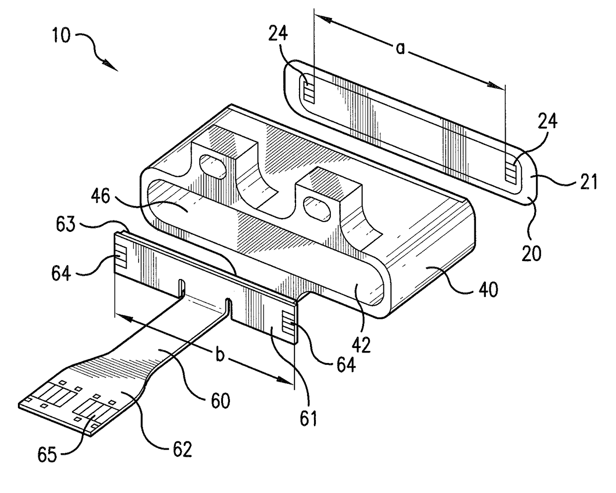
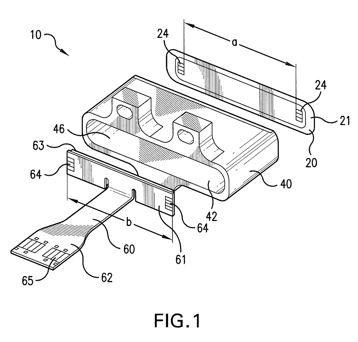
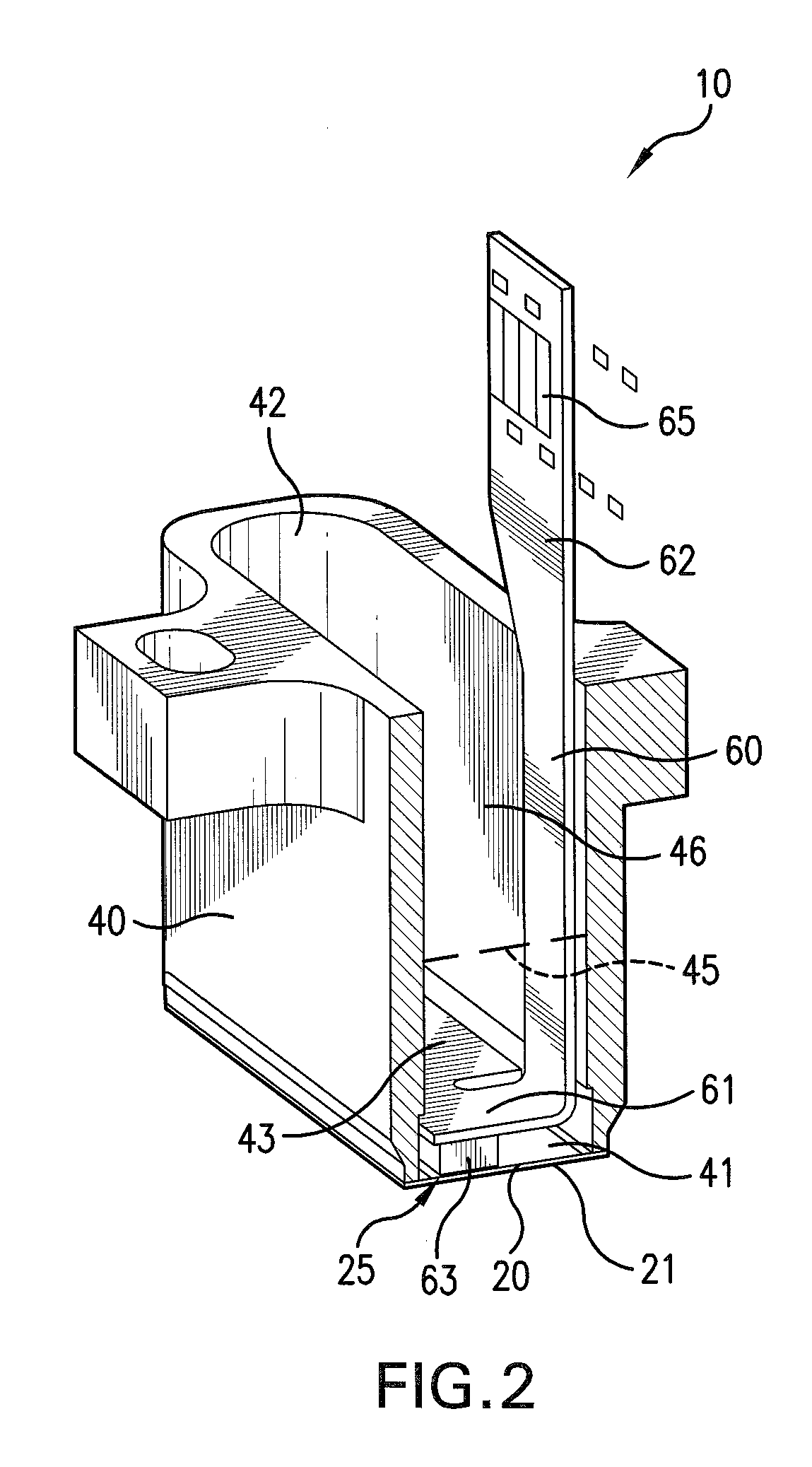
[0028]In FIGS. 1 and 2, an inductive sensor according to the present invention is labeled as a whole with the reference numeral 10. It includes a housing 40 with an oblong hole-shaped passage 46 that has a first opening 41 and second opening 42 at its ends. The housing is composed of rustproof, nonmagnetic steel and is manufactured by means of the metal-injection-molding method (MIM method).

[0029]The first opening 41 of the housing is connected to a metal plate 100 μm thick composed of rustproof, nonmagnetic steel. In FIG. 1, seven contact surfaces 24 are depicted on the metal plate, arranged in two rows. Between the contact surfaces 24, the conducting coils (now shown) are provided, which according to the exemplary embodiment in FIG. 9, are embodied in conjunction with FIG. 16 of EP 1 164 358 B1. The contact surfaces 24 are connected to the conducting coils in an electrically conductive fashion.

[0030]In addition, there is a flexible printed circuit board 60 equipped with a contacti...


PUM

PropertyMeasurementUnit
thicknessaaaaaaaaaa
distanceaaaaaaaaaa
diameteraaaaaaaaaa

Abstract

An inductive sensor has an electrically nonconductive substrate, at least one electrically conducting coil that is integrally joined to the substrate, with the mechanical rigidity of the substrate significantly greater than that of the conducting coil, a metal plate covering the conducting coil, with the substrate comprised by the metal plate, and with the surface of the metal plate on the side oriented toward the conducting coil provided with an electrically insulating layer.

Description

CROSS-REFERENCE TO A RELATED APPLICATION[0001]The invention described and claimed hereinbelow is also described in German Patent Application DE 10 2007 009 994.2 filed on Mar. 1, 2007. This German Patent Application, whose subject matter is incorporated here by reference, provides the basis for a claim of priority of invention under 35 U.S.C. 119(a)-(d).BACKGROUND OF THE INVENTION[0002]The invention relates to an inductive sensor, a position measuring system equipped with this sensor, and a method for its manufacture.[0003]An inductive sensor is known, for example, from EP 0 743 508 A2, whose FIGS. 16A and 16B show a sensor in which a number of electrical conducting coils 102, 104 are applied to a substrate 126. The conducting coils are situated in a number of layers that are electrically separated from one another by thin insulating layers 162. An insulating layer 162 is also used to cover the sensor so that the conducting coils are protected from environmental influences, e.g. fro...

Claims


Application Information

Patent Timeline
Patent Type & Authority Patents(United States)
IPC IPC(8): G01B7/14G01D5/20F16C29/00G01B7/02
CPCG01D5/2006F16C29/00G01B7/023G01B7/14Y10T29/4902
Inventor REUSING, GUENTERHOLLWECK, ROMANHAUSER, KARINSTIER, ANTONHOHNKE, FLORIAN
Owner ROBERT BOSCH GMBH
Why Eureka
Try Eureka