Bearing arrangements in a refrigeration reciprocating compressor

a reciprocating compressor and bearing arrangement technology, which is applied in the direction of positive displacement liquid engines, cranks, piston pumps, etc., can solve the problems of difficult to use variations of the usual cylindrical shape of high cost, and direct formation of the compliant region and the radial bearing regions in the crankcase b>10/b>, so as to improve the bearing conditions, reduce localized wear, and improve the effect of bearing condition

Active Publication Date: 2017-04-04
EMBRACO IND DE COMPRESSORES E SOLUCOES EM REFRIGERACAO LTDA
View PDF9 Cites 1 Cited by
  • Summary
  • Abstract
  • Description
  • Claims
  • Application Information

AI Technical Summary

Benefits of technology

[0021]In view of the operational problems mentioned above, the present invention has the object of providing bearing arrangements in a refrigeration reciprocating compressor, of the type discussed above, which allow simplifying the provision of bearing regions and avoiding, or at least reducing, the wear, by localized contact, of the radial bearing regions of the crankshaft in relation to the end portions of the bearing hub.
[0022]More specifically, the present invention has the object of avoiding, or at least reducing, said wear, compensating, at least partially, for the coaxiality deviations of the crankshaft in relation to the radial bearing in the bearing hub, and which are generally caused by geometric deviations during manufacture and assembly of said movable cooperating parts, by the compression forces of the refrigerant gas, or also by the magnetic radial forces of the rotor of the electric motor, particularly at the start of the latter.
[0023]An additional and complementary object of the present invention is to provide bearing arrangements, as mentioned above, which allow simplifying the provision of bearing regions and avoiding, or at least reducing, the wear, by localized contact, of the radial bearing regions of the crankshaft in relation to the larger eye of the connecting rod, avoiding, or at least reducing, said wear, by compensating, at least partially, for the coaxiality deviations of the crankshaft in relation to the larger eye of the connecting rod.
[0028]The construction proposed by the present invention allows substantially improving the bearing conditions, not only of the crankshaft, but also of its eccentric end portion, in the bearing hub and in the larger eye of the connecting rod, respectively, thus reducing localized wear, efficiency loss, and avoiding the increase of the starting torque in the operation of the compressor.
[0029]It should be further noted that any of said end portions of the bearing hub and of the large eye of the connecting rod, with reduced thickness, can be easily obtained without using special machining in the crankcase, in the case of the bearing hub, and without using special geometries in the process of compressing the connecting rod produced by sintering, by using bushing extensions fixed in the interior of the bearing hub and of the larger eye. The elastic radial deformation of said end portions with reduced thickness may occur due to the direct contact of the two surfaces, or by force transfer through a field of distributed pressures generated in the oil film and which separates, totally or partially, the two surfaces, an effect known as elastohydrodynamic lubrication.

Problems solved by technology

Regardless of the economically feasible type of said process, position errors will always occur, in greater or lesser extent, such as those which cause loss of orthogonality between the axis of the crankshaft 50 and the axis of the piston 30 of the mounted assembly.
It should also be observed that the formation of the compliant region and of the radial bearing regions directly in the crankcase 10 is also costly, requiring precise dimensional adjustments in the machining and finishing operations for each type of compressor, making difficult to use variations of the usual cylindrical shape of the radial bearing regions in the bearing hub 40.

Method used


Image

  • Bearing arrangements in a refrigeration reciprocating compressor
  • Bearing arrangements in a refrigeration reciprocating compressor
  • Bearing arrangements in a refrigeration reciprocating compressor

Examples


Embodiment Construction

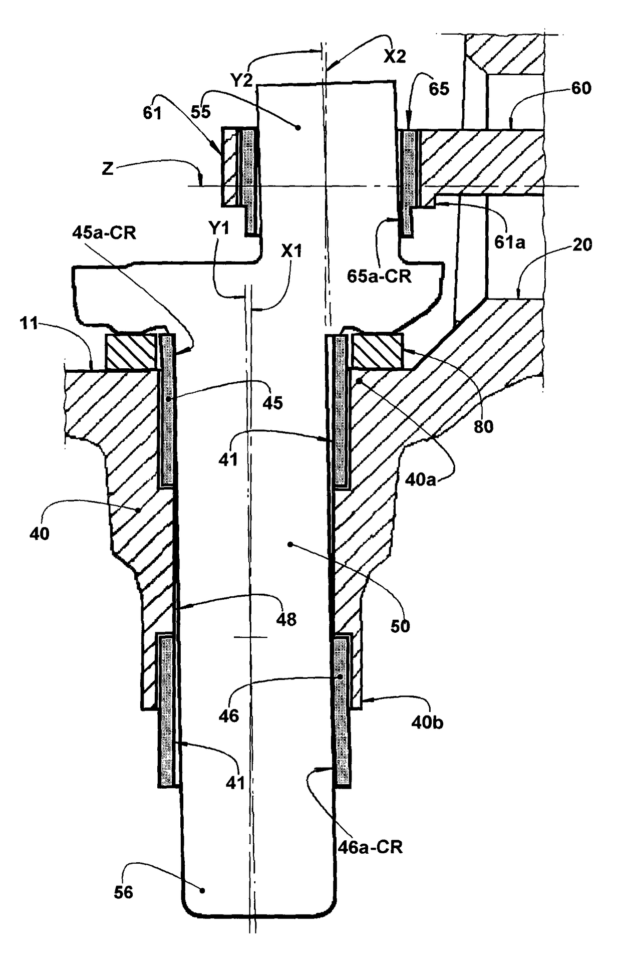
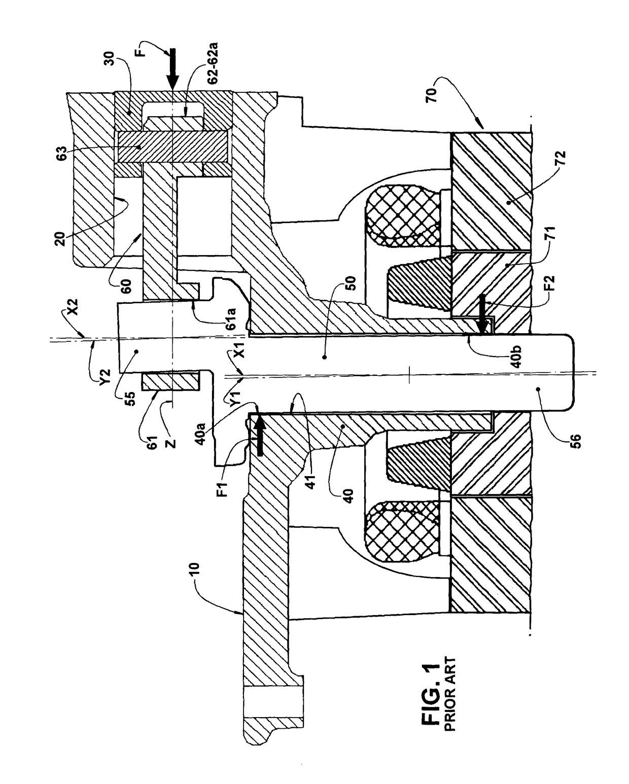
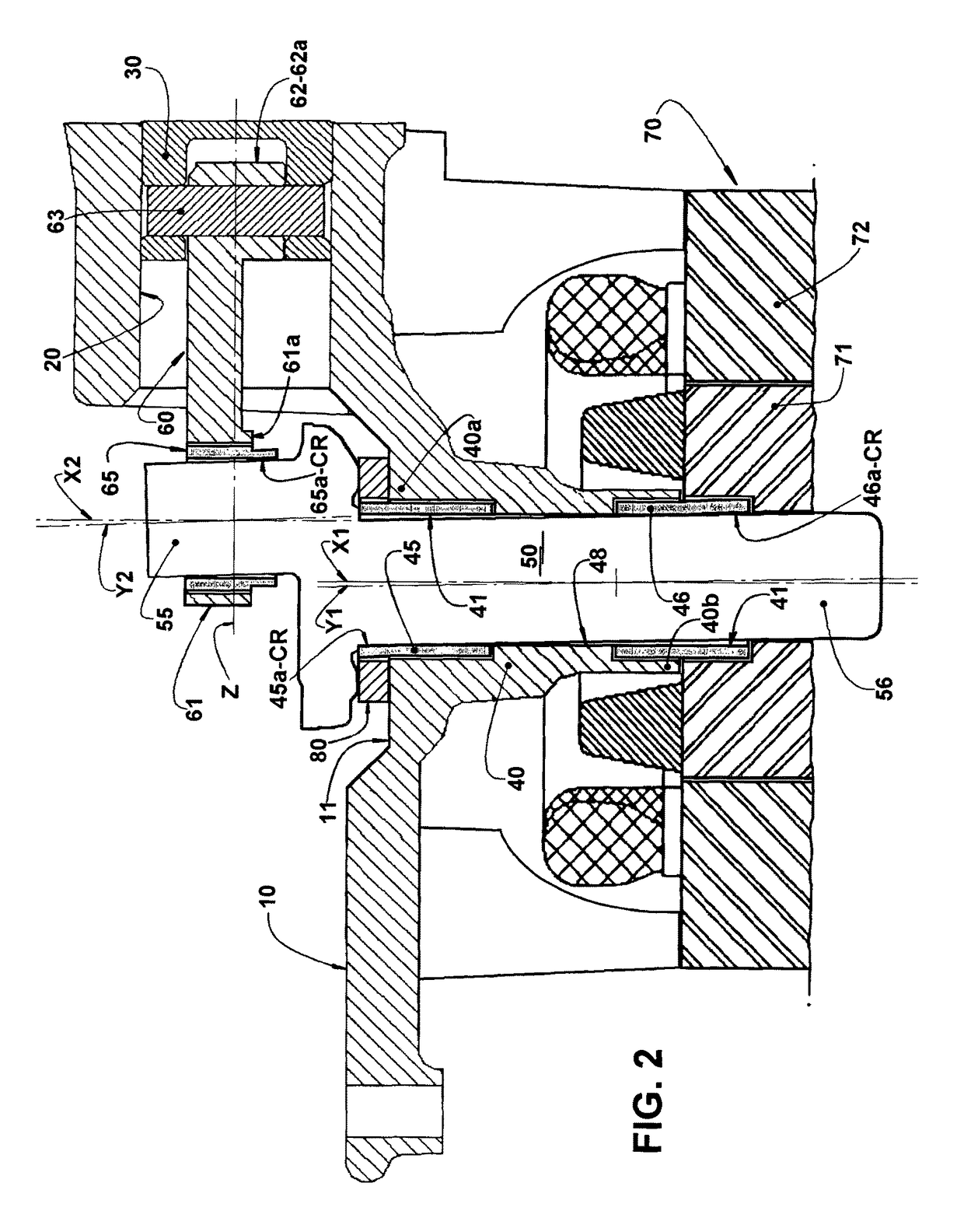
[0037]As already previously described and illustrated in FIGS. 1 and 2 of the enclosed drawings, the bearing arrangements of the present invention are applied to a refrigeration compressor of the type which comprises, in the interior of a shell (not illustrated), a crankcase 10 defining, generally in a single cast piece, a cylinder 20 having an axis Z, and a bearing hub 40 which defines, internally, a radial bearing 41 having an axis X1.

[0038]A crankshaft 50, having an axis Y1, is mounted in the interior of the radial bearing 41 of the bearing hub 40 and has an eccentric end portion 55, with an axis Y2 projecting outwards from a first end portion 40a of the bearing hub 40, and a free end portion 56 which projects outwards from a second end portion 40b of the bearing hub 40.

[0039]A piston 30 is housed in the cylinder 20, so as to be displaced therein, in a reciprocating movement, by a connecting rod 60 which has an end defining a larger eye 61, mounted around the eccentric end portio...


PUM

PropertyMeasurementUnit
radial thicknessaaaaaaaaaa
friction coefficientaaaaaaaaaa
compression forceaaaaaaaaaa

Abstract

The compressor comprises: a crankcase (10) carrying a cylinder (20) and a bearing hub (40) having a first and a second end portions (40a, 40b) and defining a radial bearing (41), in which is housed a crankshaft (50); and a connecting rod (60) coupled to a piston (30) housed in the cylinder (20) and having a larger eye (61) mounted in an eccentric end portion (55) of the crankshaft (50). Each of said end portions (40a, 40b) is defined by a bushing extension (45, 46) affixed in the interior of the bearing hub (40) and having an end portion (45a, 46a) projecting outwards from the bearing hub (40), in order to be elastically and radially deformed when pressed by a confronting portion of the crankshaft (50), which presents coaxiality deviation in relation to the axis (X1) of the radial bearing (41).

Description

CROSS-REFERENCE TO RELATED APPLICATIONS[0001]This application is the U.S. national phase of PCT / BR2013 / 000383 filed Aug. 1, 2013, which claims priority of Brazil Patent Application 10 2012 025039 0 filed Oct. 1, 2012, which is incorporated herein by reference.FIELD OF THE INVENTION[0002]The present invention refers to bearing arrangements introduced in radial bearing regions associated with the crankshaft of a refrigeration reciprocating compressor, either hermetic or not, in order to allow said radial bearing regions to undergo a controlled deformation, so as to compensate, at least in part, for the deviations in the nominal relative positioning of the cooperating parts, caused by misalignments in the manufacture or assembly of said cooperating parts, or by forces acting thereon and resulting from the operation of the electric motor of the compressor or from compression of the refrigerant gas.PRIOR ART[0003]A conventional construction for the refrigeration compressor of the recipro...

Claims


Application Information

Patent Timeline
Patent Type & Authority Patents(United States)
IPC IPC(8): F16C33/22F16C9/03F16C33/20F04B9/04F16C33/12F16C33/10F16C25/04F04B39/00F16C3/22F16C3/14F16C3/08
CPCF16C33/1025F16C33/121F16C33/125F16C33/128F16C33/20F16C33/205F16C25/04F04B9/045F04B39/0094F16C3/22F16C9/03F16C33/10F16C33/106F16C3/08F16C3/14F16C2208/20F16C2208/58F16C2223/60F16C9/02
Inventor MANKE, ADILSON LUIZPUFF, RINALDOSACOMORI, DIEGO
Owner EMBRACO IND DE COMPRESSORES E SOLUCOES EM REFRIGERACAO LTDA
Why Eureka
Try Eureka