Intramedullary compression rod

a technology of bone fracture and rod, which is applied in the field of devices and methods for fixing and compressing bone fractures, can solve the problems of difficult to fix the rod to the bone, and the forearm using this type of device, so as to stabilize the fracture and reduce the damage to the overlying soft tissues

Active Publication Date: 2017-04-18
MERRELL GREGORY
View PDF24 Cites 2 Cited by
  • Summary
  • Abstract
  • Description
  • Claims
  • Application Information

AI Technical Summary

Benefits of technology

[0006]A device and method of stabilizing a fracture of a bone is provided. The device may include an intramedullary rod. The distal end (furthest away from the body) of the rod is shaped to engage a distally placed screw, and a proximal end (nearest the body) of the rod may include through holes to receive fixation screws. The device may further include an insertion jig that detachably connects to the proximal end of the rod and may be used to apply a compressive force to the fracture site whereby displaced fractures may be closed. The jig may also be used to correctly place proximal end fixation screws in a proximal end of the rod. Among other advantages, the device provides an intramedullary rod that achieves fixation of the rod to the bone on opposed sides of the fracture regardless of rod or bone diameter, providing rotational control of the fracture, and also allows for compression at the fracture site. In addition, fixation of the rod to the bone is accomplished without requiring a precise alignment of a distal end fixation screw. Still further, the device uses headless fixation screws, which, when in place, are disposed below cortical surface of bone, reducing damage to overlying soft tissues.
[0024]The step of inserting a first screw further includes inserting the first screw to the extent that an end of the first screw contacts the sliding surface of the rod, and the other end of the screw is engaged with cortical bone. After the step of further actuating the compression generating device, the method further includes advancing the first screw until a surface of the rod contacts an interior surface of the medullary cavity. After the rod insertion jig is detached from the second end of the rod, the second end of the rod resides at or below the cortex of the bone. After insertion, at least one of the first screw and one or more second screws is seated at or below the cortex of the bone. The step of further actuating the compression generating device is continued until a compression force is applied to the bone at the fracture. The first screw comprises a flat tip, and wherein when the flat tip is in contact with the sliding surface of the rod, rotation of the rod relative to the bone is prevented.

Problems solved by technology

However, it is difficult to fix smaller diameter long bones such as the ulna of the forearm using this type of device because of the small bone diameter.
As a result, it is difficult to fix the rod to the bone.

Method used


Image

  • Intramedullary compression rod
  • Intramedullary compression rod
  • Intramedullary compression rod

Examples


Embodiment Construction

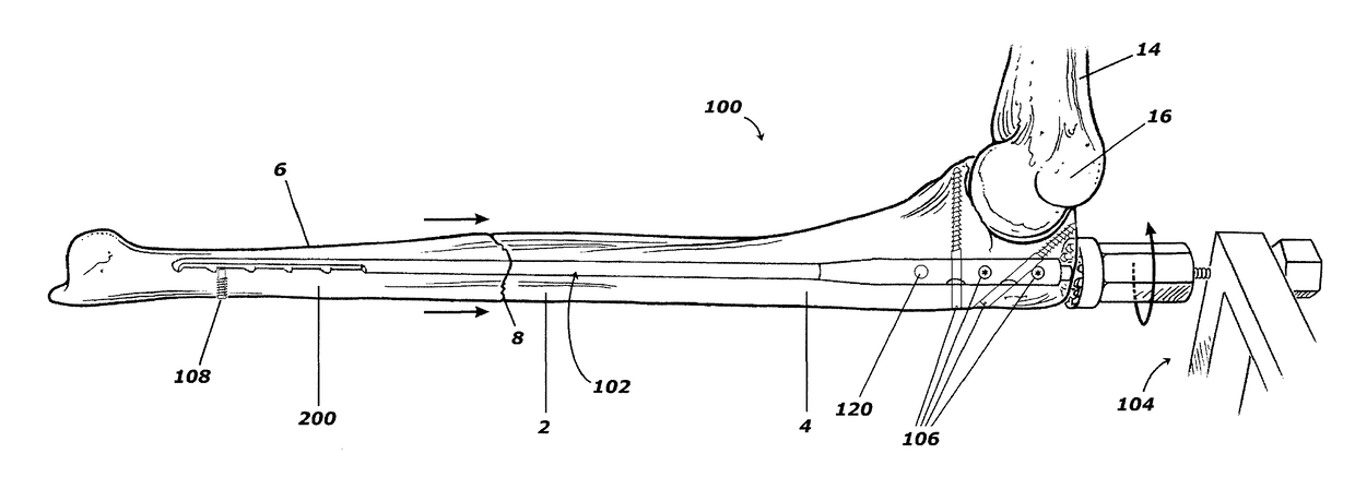
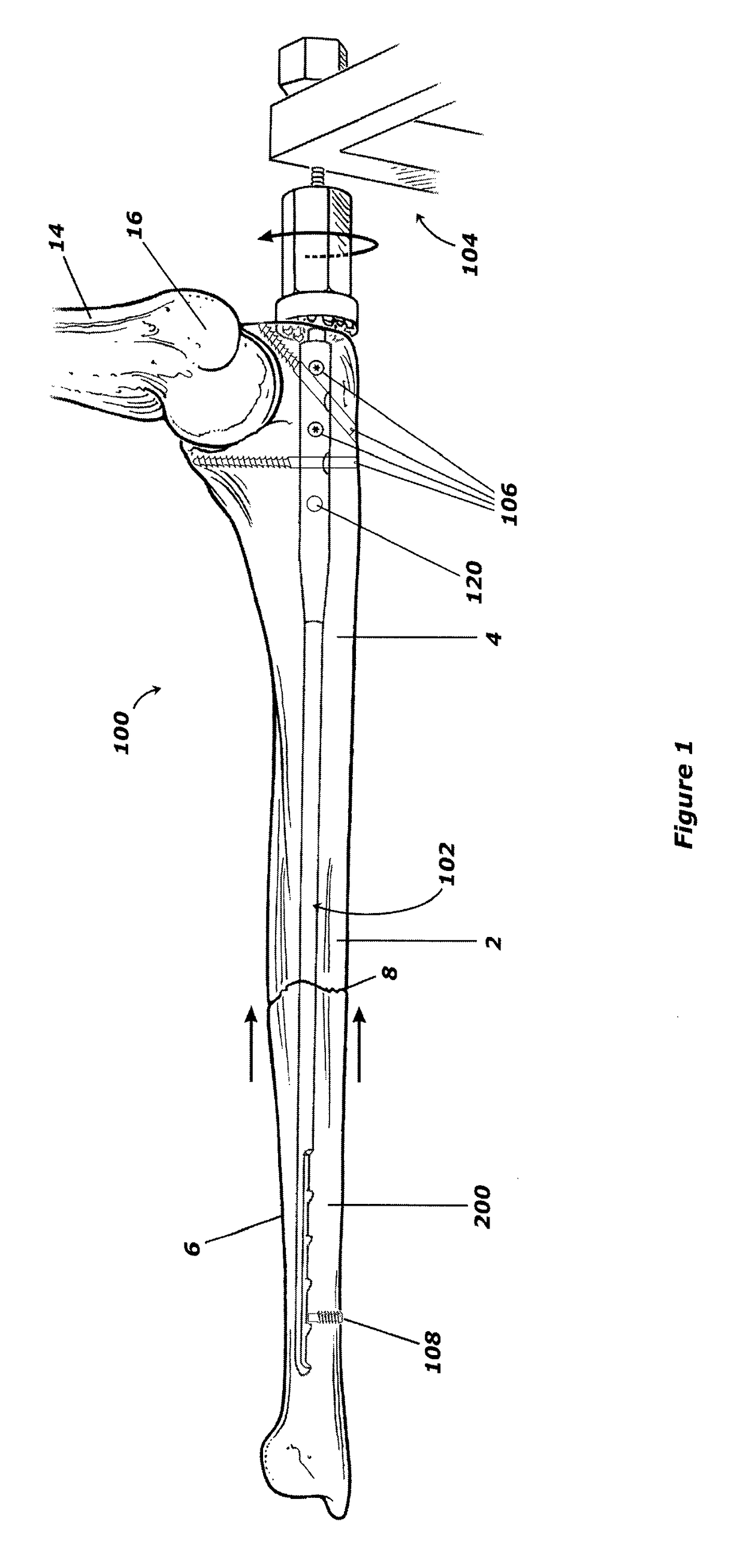
[0046]Referring to FIG. 1, an ulna 2 is shown connected to a humerus 14 via an elbow joint 16. A fracture 8 is shown in the mid-shaft of the ulna 2, dividing the ulna 2 into a proximal bone portion 4 and a distal bone portion 6. A compression device 100, including an intramedullary rod 102 and rod insertion jig 104, is shown with the rod 102 disposed within the medullary canal 200 (FIGS. 4, 13) of the ulna 2. The rod 102 is fixed relative to the distal bone portion 6 using a distal screw 108, and is fixed relative to the proximal bone portion 4 using one or more proximal interlock screws 106. When used in combination with the rod insertion jig 104, the rod 102 serves to compress the proximal and distal bone portions 4, 6 of the ulna 2 together. Once the proximal and distal bone portions 4, 6 are properly mutually positioned, the rod insertion jig 104 may be disconnected from the rod 102, and the rod 102 remains within the medullary canal 200 of the ulna 2 to provide compression and ...


PUM


Abstract

A device and method of stabilizing a fracture of a bone is provided. The device includes an intramedullary rod having a shaped distal end, and an insertion jig detachably connectable to the proximal end of the rod and used with the rod to apply a compressive force to the fracture site. The jig may also be used to correctly place fixation screws in a proximal end of the rod. The device achieves both fixation of the rod to the bone regardless of rod or bone diameter and allows for compression at the fracture site. In addition, fixation of the rod to the bone is accomplished without requiring a precise alignment of a distal end fixation screw. The device uses headless fixation screws, which, when in place, are disposed below cortical surface of bone, reducing damage to overlying soft tissues.

Description

BACKGROUND OF THE INVENTION[0001]Field of the Invention[0002]This invention relates to devices and methods for fixation and compression of bone fractures.[0003]Description of the Background Art[0004]It is well known to use rigid internal fixation devices including rods, plates and wires to position and stabilize fractures of the long bones of the body to achieve successful bone healing. Known internal fixation devices are typically fixed to a bone using one or more screws. In some fractures of the long bones, a common approach for aligning the bone fragments is to insert a rod through the intradullary cavity. The rod may be held in place by screws until the fracture has healed, or may be left in the bone after healing is complete.[0005]Conventional intramedullary rods, such as those used in the femur, often include an elongate rod that extends across the fracture and is fixed to the bone on each side of the fracture using screws that pass through holes provided in the rod. However, ...

Claims


Application Information

Patent Timeline
Patent Type & Authority Patents(United States)
IPC IPC(8): A61B17/72A61B17/17
CPCA61B17/1739A61B17/72A61B17/7225A61B17/1725A61B17/7283
Inventor MERRELL, GREGORY
Owner MERRELL GREGORY
Why Eureka
Try Eureka