Heating furnace system for hot stamping

a heating furnace and hot stamping technology, applied in the field of hybrid heating furnace systems for hot stamping, can solve the problems of increasing various expenses, reducing process speed and production cost, and unable to avoid surface oxidation of steel plates, so as to reduce the length of an electric furnace, reduce the space required for facilities, and reduce the effect of fuel cos

Active Publication Date: 2017-04-25
MYUNGSHIN IND CO LTD +1
View PDF11 Cites 11 Cited by
  • Summary
  • Abstract
  • Description
  • Claims
  • Application Information

AI Technical Summary

Benefits of technology

[0010]An aspect of the present invention is to provide a hybrid heating furnace system for hot stamping, in which a high-frequency heating furnace is combined with an electric furnace (or a gas furnace) in order to make facilities small and improve productivity.
[0023]According to embodiments of the present invention, the heating furnace system for hot stamping can reduce space required for facilities by 50% or more compared to the related art, fuel cost due to a decrease in the length of an electric furnace, and the unit cost of a hot stamped part.
[0024]Further, the heating furnace system can not only properly adjust outputs of inverters in the first heating furnace to gradually increase temperature of a steel plate, but can also prevent deformation caused by sharp heating of the steel plate due to use of a plurality of pairs of upper and lower rolls, and minimize deformation during the transfer of the steel plate.
[0025]In addition, high-frequency coils are alternately installed with pairs of upper and lower rolls, so that they can perform direct induction heating on the steel plate. During high-frequency heating, it is possible to minimize a high-frequency influence on other parts than the steel plate.

Problems solved by technology

In contrast, the hot stamping technology has disadvantages in that it cannot avoid surface oxidation of the steel plate due to a high-temperature process, and that it must perform a separate descaling process 30 on formed products as illustrated in FIG. 1.
In this manner, the heating furnaces such as electric furnaces or gas furnaces increase heating time, and thus cause a decrease in process speed and an increase in production cost.
These large facilities increase various expenses.
However, in the case of the heating furnace based on the high-frequency induction heating (hereinafter, referred to as “high-frequency furnace”), the heating furnace has a problem of a sharp increase in temperature or deformation during transferring the steel plate.

Method used


Image

  • Heating furnace system for hot stamping
  • Heating furnace system for hot stamping
  • Heating furnace system for hot stamping

Examples


Embodiment Construction

[0037]A heating furnace system for hot stamping according to an exemplary embodiment of the present invention will be described below with reference to the accompanying drawings.

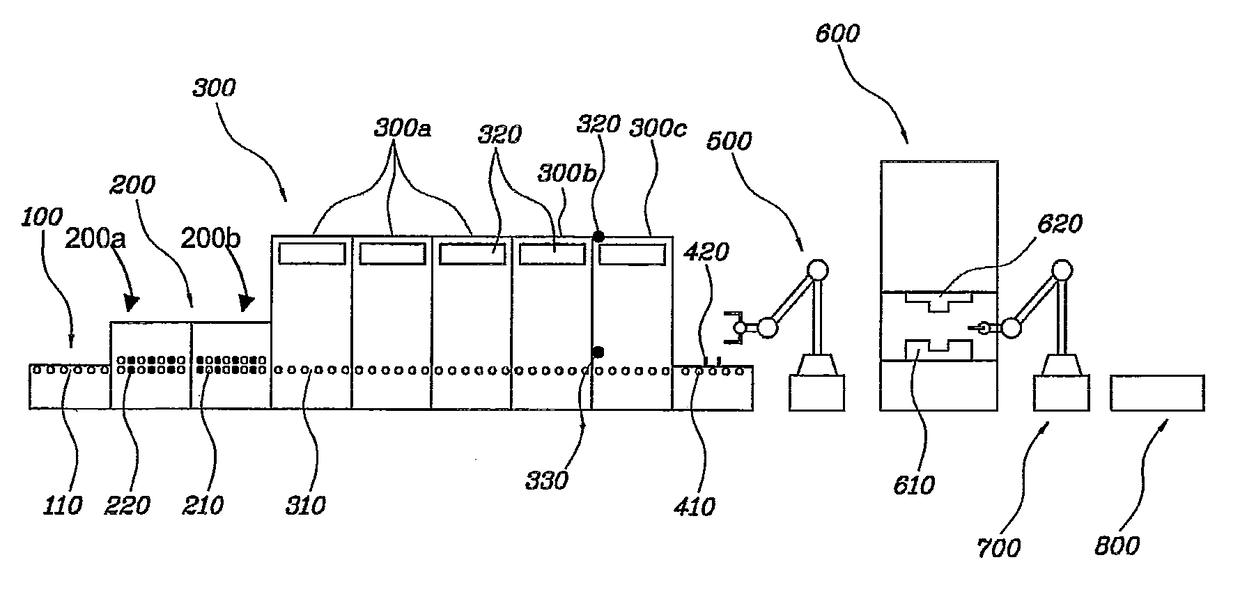
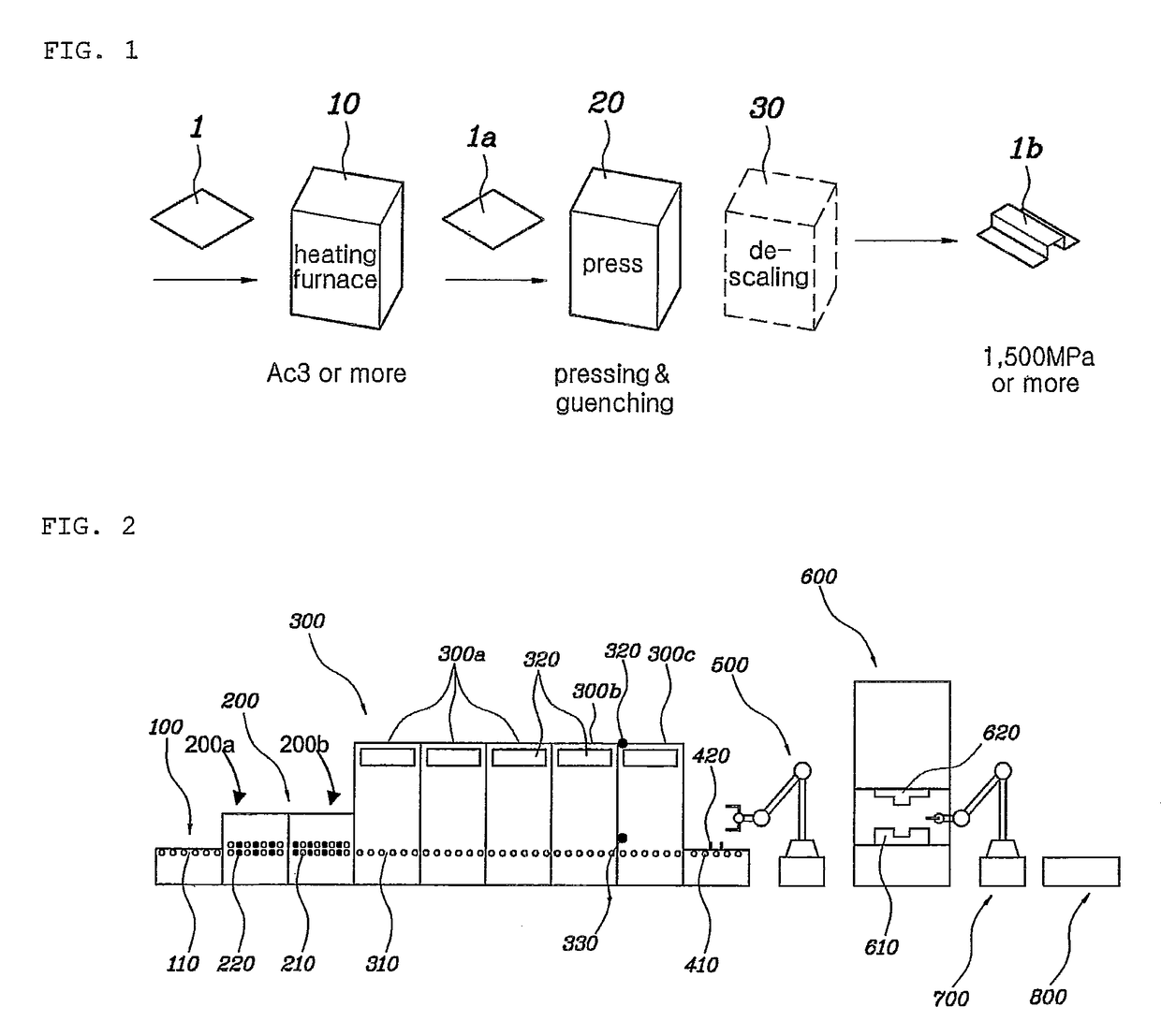
[0038]Referring to FIG. 2, a hot stamping process comprises heating a steel plate in a heating furnace system, forming and cooling the heated steel plate in a press 600, and loading the pressed steel plate onto a conveyor 800. Transfer robots 500 and 700 are positioned to transfer the steel plate (or a product) between the heating furnace system and the press 600, and between the press 600 and the conveyor 800, respectively.

[0039]The heating furnace system includes a steel plate feed section 100, heating furnaces 200 and 300, and a discharge section 400. The heating furnaces 200 and 300 are sorted into a first heating furnace 200 and a second heating furnace 300.

[0040]As illustrated in FIG. 2, the steel plate feed section 100 includes a plurality of feed rolls 110 arranged in a lengthwise direction in order ...


PUM

PropertyMeasurementUnit
temperatureaaaaaaaaaa
thickaaaaaaaaaa

Abstract

In a heating furnace system for hot stamping, a first heating furnace has a plurality of pairs of upper and lower rolls arranged in a lengthwise direction thereof in order to transfer a steel plate, and high-frequency coils alternately arranged with the pairs of upper and lower rolls in the lengthwise direction thereof. A second heating furnace continuously transfers the steel plate from the first heating furnace during heating the steel plate at temperature of Ac3 or more, and has a plurality of transfer rollers arranged in a lengthwise direction thereof. The second heating furnace includes an electric furnace or a gas furnace. This heating furnace system can reduce space required for facilities by 50% or more compared to the related art.

Description

CLAIM OF PRIORITY[0001]This application claims the priority of Korean Patent Application No. 10-2008-0096912, filed on Oct. 2, 2008, in the Korean Intellectual Property Office, the disclosure of which is incorporated herein by reference.BACKGROUND OF THE INVENTION[0002]Field of the Invention[0003]The present invention relates to a hybrid heating furnace system for hot stamping, in which a high-frequency heating furnace is combined with an electric furnace (or a gas furnace).[0004]Description of the Related Art[0005]In vehicle manufacturing fields, there has been a focus on a decrease in weight and an increase in strength. Recently, hot stamping technology has been located at the center of this focus. The hot stamping technology was proposed by Norrbottens Jarnverk AB in Sweden in the early 1970s. In GB Patent No. 1490535 issued to this company, the hot stamping technology is disclosed in detail.[0006]Referring to FIG. 1, the hot stamping technology is characterized by manufacturing ...

Claims


Application Information

Patent Timeline
Patent Type & Authority Patents(United States)
IPC IPC(8): H05B6/10F27D99/00C21D9/46F27B9/10F27B9/24F27B9/36C21D1/42H05B6/16C21D8/02
CPCC21D1/42C21D8/0205C21D9/46F27B9/10F27B9/2407F27B9/36F27D99/0006F27D2099/0061Y02P10/253Y02P10/25C21D9/00
Inventor HWANG, JUNG BOKKIM, SUN UNGKIM, WON HYUCKYOO, SEUNG JOLEE, HYUN WOO
Owner MYUNGSHIN IND CO LTD
Why Eureka
Try Eureka