Device for producing particles and method for producing particles

a technology of a device and a particle, which is applied in the direction of liquid-liquid reaction process, crystal auxillary selection, separation process, etc., can solve the problems of high power and economic cost, insufficient contact efficiency to the target only by spiral flow, and local reaction to readily give crystals irregular in size and shape, etc. , to achieve the effect of uniform size and shape, low power cost and small facilities

Active Publication Date: 2019-10-08
TSUKISHIMA KIKAI CO LTD
View PDF29 Cites 0 Cited by
  • Summary
  • Abstract
  • Description
  • Claims
  • Application Information

AI Technical Summary

Benefits of technology

[0040]According to the present invention, the resulting particles can have uniform sizes and shapes. There is also an advantage that the particles can be produced at the low power cost.
[0041]Furthermore, particles having a small particle size and a sharp particle size distribution can be prepared. A large amount of reaction processing per unit time can be achieved with small facilities.

Problems solved by technology

Unfortunately, in the production of particles in this stirred reactor, the diffusion of the solution of the reactants is the rate-determining factor, causing local reaction to readily give crystals irregular in size and shape.
In addition, preparation of fine particles needs to increase the rotation speed of the stirring blade, which requires high power and is not economical.
Although the reactor of Patent Literature 2 has an advantage of a high contact efficiency of the chlorine gas by virtue of the spiral flow, the contact efficiency to the target only by the spiral flow is not sufficient.
However, the inventors have found that this crystallizer exhibited a limited improvement because it used only a spiral flow.

Method used


Image

  • Device for producing particles and method for producing particles
  • Device for producing particles and method for producing particles
  • Device for producing particles and method for producing particles

Examples


examples

[0129]Advantageous effects of the present invention will be clarified by the following examples and comparative examples.

(Production of Zinc Hydroxide)

[0130]In this example, zinc sulfate adjusted to 1 mol / L and 25% sodium hydroxide were injected into a reactor for the following reaction to produce zinc hydroxide:

ZnSO4+2NaOH→Zn(OH)2+Na2SO4

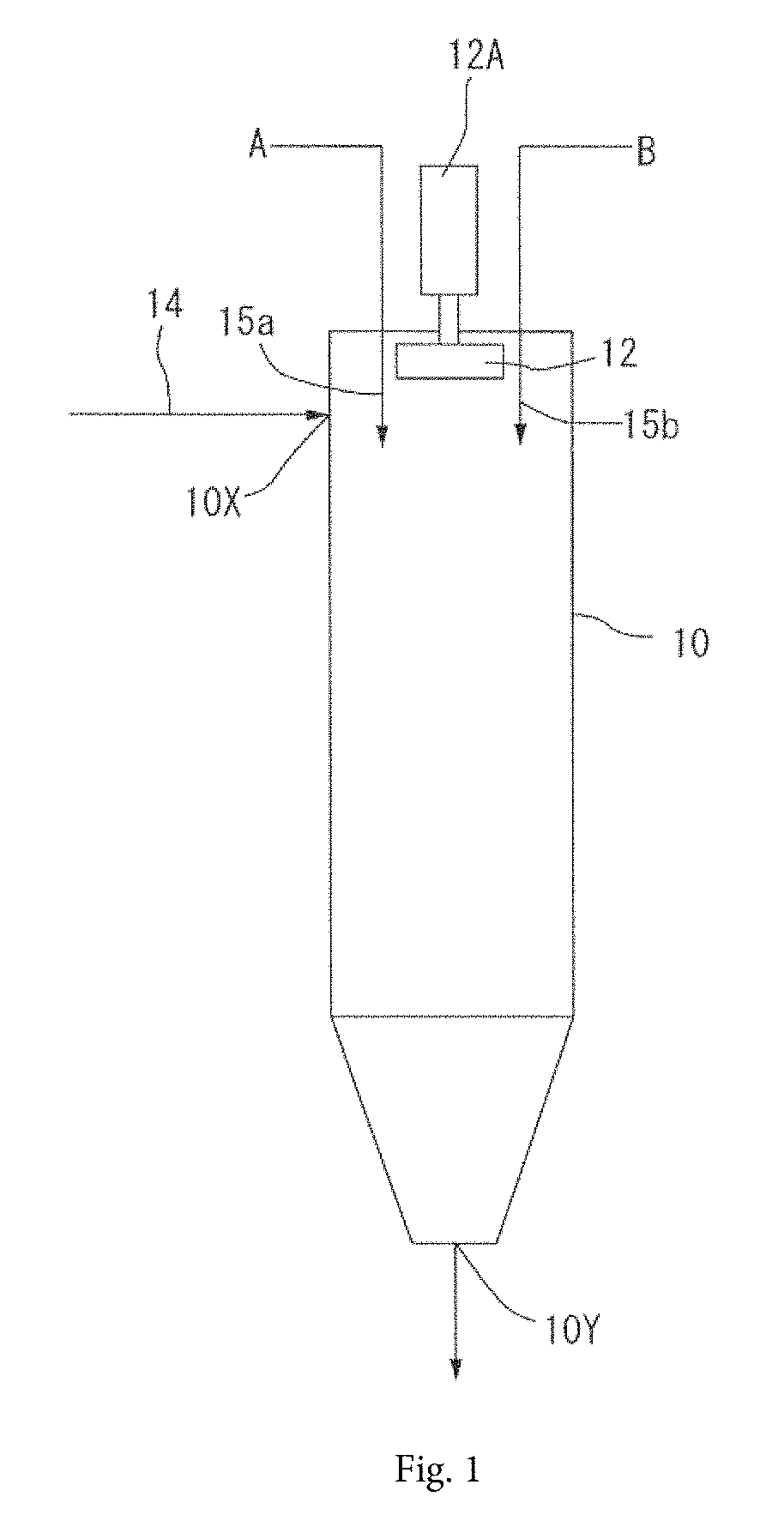
[0131]Table 1 shows the results of comparative evaluation after 180 minutes of an operation under conditions of 20° C., a pH of 12.5, an installed capacity of 5 L, and an average retention time of 30 min. The inlet diameter of the reactor was 13 mm.

[0132]The term “average retention time” is synonymous with the liquid injection time necessary for filling the operational capacity of the reactor and is that when zinc sulfate and sodium hydroxide were injected at 167 mL / min in total.

[0133]

TABLE 1Run No.123456Exam-ComparativeExam-ComparativeExam-Comparativeple 1Example 1ple 2Example 2ple 3Example 3Target particlesZn(OH)2Zn(OH)2Zn(OH)2Zn(OH)2Al2(OH)3Al2(...


PUM

PropertyMeasurementUnit
inflow velocityaaaaaaaaaa
diameteraaaaaaaaaa
pHaaaaaaaaaa

Abstract

A method of producing particles by bringing plural dissimilar materials A and B into contact with each other includes feeding a liquid into a reactor from a first end portion of the reactor such that the liquid flows along the inner peripheral surface of the reactor and generating a vortex flow toward a second end portion in the reactor by the feed of the liquid; disposing a flow-assisting blade capable of rotating around the central axis line in the reactor and rotating the flow-assisting blade; and injecting materials to be contacted A and B into the reactor, discharging a contacted liquid from the second end portion of the reactor, and generating the particles in the contacted liquid.

Description

CROSS-REFERENCE TO RELATED APPLICATIONS[0001]This application is the U.S. national stage application of International Application PCT / JP2017 / 000531, filed Jan. 11, 2017, which international application was published on Aug. 3, 2017, as International Publication WO 2017 / 130687 in the Japanese language. The International Application claims priority of Japanese Patent Application No. 2016-013593, filed Jan. 27, 2016. The international application and Japanese application are both incorporated herein by reference, in entirety.TECHNICAL FIELD[0002]The present invention relates to a device for producing particles and a method of producing particles.BACKGROUND ART[0003]The industrial fields of cosmetics, catalysts, electronic materials, battery materials, fine ceramics, pharmaceuticals, and foods involve production of particles, in particular, fine particles.[0004]In general, two or more reactants are fed in a stirred reactor equipped with a stirrer, the reactants are mixed in a liquid to ...

Claims


Application Information

Patent Timeline
Patent Type & Authority Patents(United States)
IPC IPC(8): B01J19/00B01F5/00B01J10/00B01J19/18B01F5/10B01F7/16B01F7/26B01J14/00B01F3/08C01F7/34B01D9/02B01D9/00C01F11/18C01G9/02C07C227/42C07C229/08B01F27/93
CPCB01J19/0066B01F3/08B01F7/26B01J19/1837B01J10/00B01F5/10B01J14/00C07C227/42B01D9/02B01J19/00B01F5/0065C01F11/18C01G9/02C07C229/08B01F7/16C01F7/34B01D9/005B01F2005/0017B01J2219/1943B01J2219/185B01F2005/004B01D2009/0086B01J2219/00166B01J2204/002B01J2/006B01F23/40B01F25/50B01F27/93B01F27/80B01D3/08B01J19/1875B01J2219/00452B01J2219/00481B01J2219/00599B01F25/103B01F2025/913B01F2025/9191
Inventor DOYA, YO
Owner TSUKISHIMA KIKAI CO LTD
Why Eureka
Try Eureka