
Humidification cell

a technology of humidification cell and membrane, which is applied in the direction of fuel cells, electrical appliances, electrochemical generators, etc., can solve the problems of partial masking of the membrane by the outer plates in the region of the supporting elements, blockages at critical narrow points, and restricted functionality of fuel cells, so as to avoid the problem of impaired humidification capacity and corrosion, the effect of less rigidity

Inactive Publication Date: 2017-04-25
SIEMENS AG
View PDF11 Cites 0 Cited by
  • Summary
  • Abstract
  • Description
  • Claims
  • Application Information

AI Technical Summary

Benefits of technology

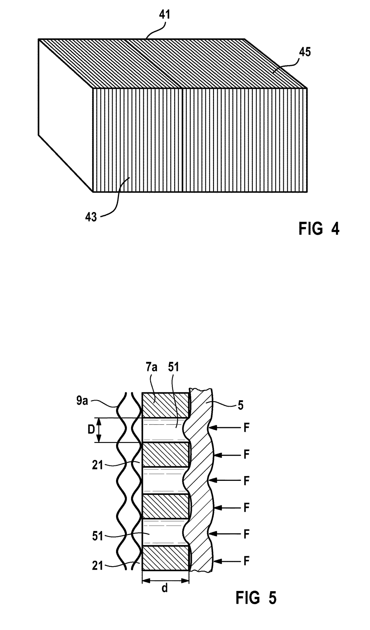
The present invention relates to a humidification cell that can prevent corrosion and impaired humidification capacity. The invention achieves this by use of a screen fabric and membrane that are matched in terms of pore size and rigidity to the pressures in the chambers adjoining the membrane. This prevents the membrane from coming into contact with the outer plate, which could cause problems. The screen fabric is highly mechanical and is able to support a corrosion-proof carbon paper outer plate. The membrane has pores with a diameter and thickness that provide good mechanical strength and humidification capacity. The screen fabric is securely mounted and the humidification cell has a simple structure with good stability and insensitive to pressure. The support element can cover the entire area of the membrane or just part of it, ensuring proper membrane support and increased humidification capacity.

Problems solved by technology

As measurements surprisingly show, it is also possible to achieve 100% gas humidification with a screen fabric, without liquid water in the form of water droplets being entrained by the operating gas in the gas chamber, which may lead to restricted functionality of fuel cells due to the introduction of water.
Since the screen fabric is produced by a yarn weaving process and not from short fibers, short fibers cannot become detached, as when carbon paper is used, which may lead to blockages at critical narrow points.
Irrespective of whether the membrane is connected firmly with the support element(s) or is clamped detachably between the support elements, partial masking of the membrane by the outer plates in the region of the support elements is not possible.

Method used


Image

  • Humidification cell
  • Humidification cell
  • Humidification cell

Examples


Embodiment Construction

[0027]Identical items are provided with identical reference numerals in the figures.

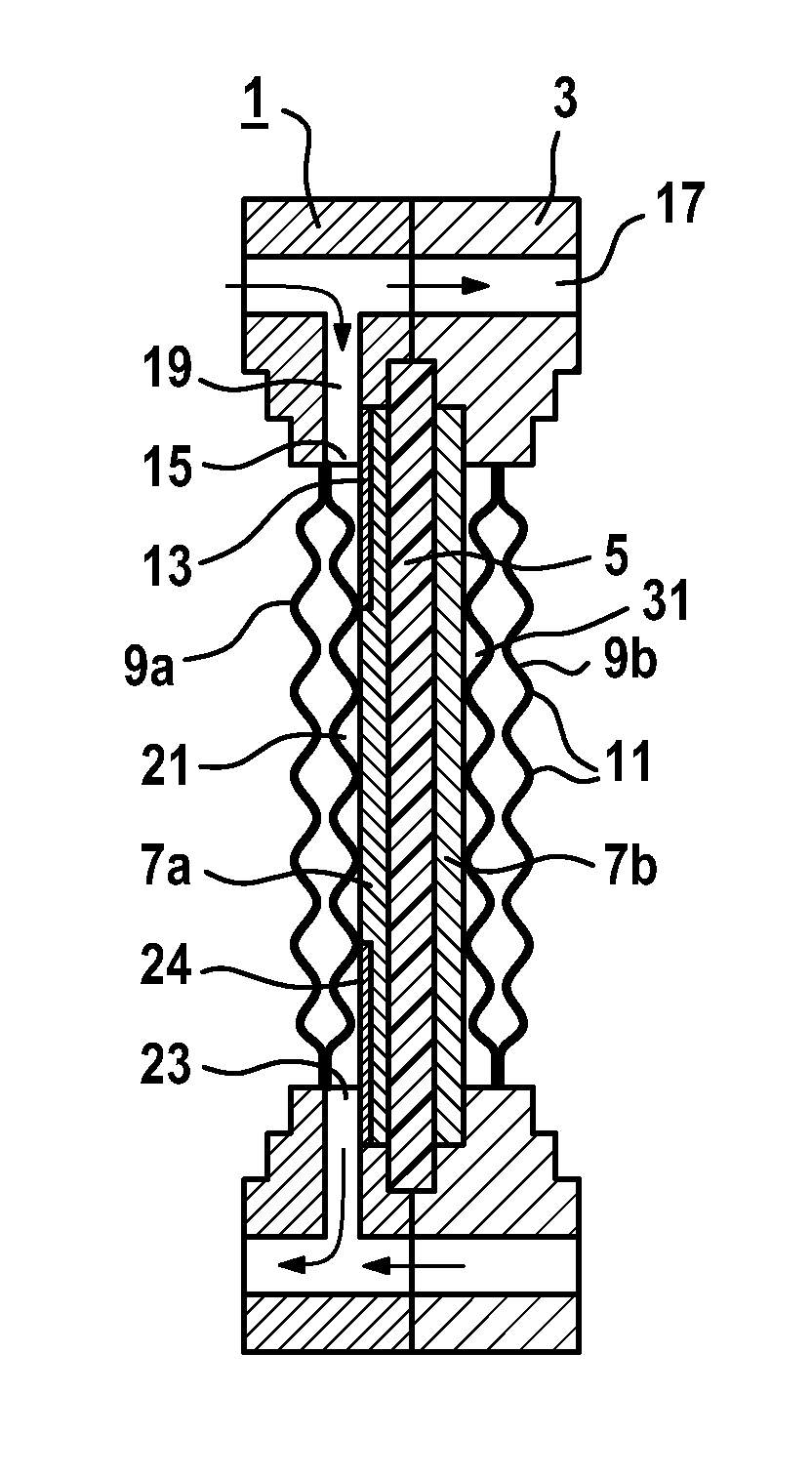
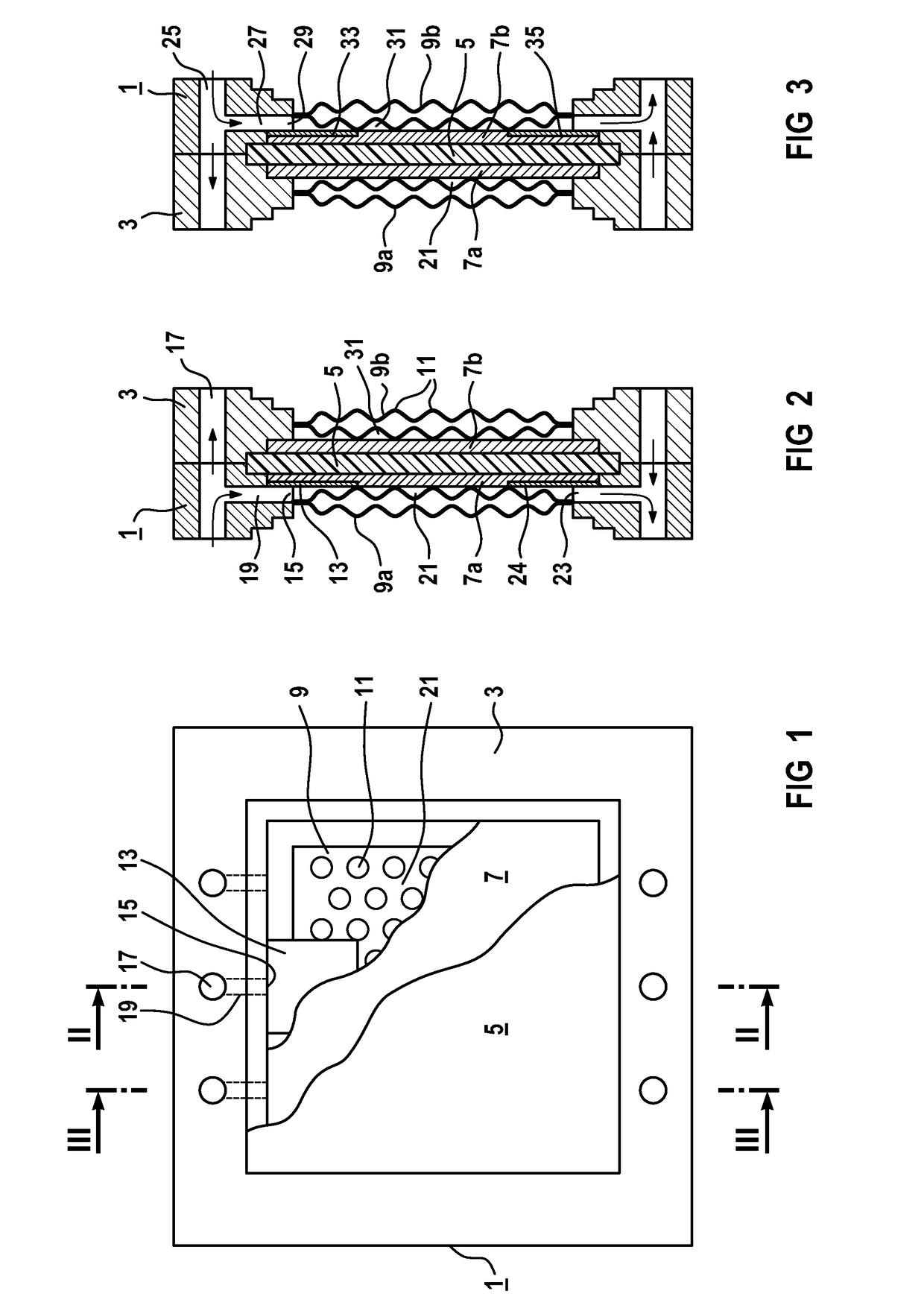
[0028]FIG. 1 is a schematic plan view of the basic structure of a rectangular and planar humidification cell 1, which comprises a membrane 5 embedded in a frame of a sealing material 3 and shown cut open. Under the membrane 5 a support element 7 is visible, likewise cut open. Under the support element 7 an outer plate 9 is illustrated, which takes the form of a metal sheet with an embossed structure 11. The embossed structure 11 consists of round elevations or wells within the outer plate 9. Between the outer plate 9 and the support element 7 a masking device 13 is fitted. The masking device 13 is arranged in the region of an operating medium inlet 15.

[0029]FIG. 2 shows a section through the humidification cell 1 along the line II-II, wherein here in each case, however, a support element 7a or 7b respectively and an outer plate 9a or 9b respectively are arranged either side of the membrane 5. In deta...


PUM

PropertyMeasurementUnit
diameteraaaaaaaaaa
diameteraaaaaaaaaa
thicknessaaaaaaaaaa

Abstract

A humidification cell of a fuel cell apparatus includes a first outer plate and a second outer plate. A gas chamber, a humidification chamber and a water-permeable membrane separating the two chambers, are disposed between the first outer plate and the second outer plate, starting from the first outer plate. A first water-permeable support element that prevents fibers from detaching and also prevents medium flows from blocking narrow gas outlets, is disposed between the first outer plate and the membrane in such a way that the first support element is made of a filter material.

Description

BACKGROUND OF THE INVENTIONField of the Invention[0001]The invention relates to a humidification cell of a fuel cell apparatus. The humidification cell includes a first outer plate and a second outer plate. A gas chamber, a humidification water chamber and a water-permeable membrane separating the two chambers, are disposed between the first outer plate and the second outer plate, starting from the first outer plate. A first water-permeable support element is disposed between the first outer plate and the membrane. Such a humidification cell is known for example from EP 1 435 121 B1.[0002]In a fuel cell electrical power is generated highly efficiently by the electrochemical combination of hydrogen (H2) and oxygen (O2) on an electrolyte, yielding water (H2O). The industrial implementation of this fuel cell principle has led to different solutions, specifically with different electrolytes and operating temperatures of between 60° C. and 1000° C. As a function of their operating temper...

Claims


Application Information

Patent Timeline
Patent Type & Authority Patents(United States)
IPC IPC(8): H01M8/04119H01M8/1018
CPCH01M8/04149H01M2008/1095Y02E60/50
Inventor BRANDT, TORSTENDATZ, ARMINHAMMERSCHMIDT, ALBERTLATZEL, SILKELERSCH, JOSEFMATTEJAT, ARNOSTUEHLER, WALTERVOITLEIN, OTTMAR
Owner SIEMENS AG
Learn More