
Door handle arrangement for a motor vehicle

a technology for motor vehicles and handles, applied in the direction of door/window fittings, mechanical devices, lock applications, etc., can solve the problems of inadvertent movement of handles, blocked, applied forces,

Active Publication Date: 2017-05-02
HUF HULSBECK & FURST GMBH & CO KG
View PDF5 Cites 2 Cited by
  • Summary
  • Abstract
  • Description
  • Claims
  • Application Information

AI Technical Summary

Benefits of technology

[0007]Therefore, the invention is based on the objective of providing in a constructively simple and cost-effective manner a door handle arrangement in which the locking device reliably and securely blocks the handle or the coupling device even when alternating accelerating forces occur during a collision.
[0010]The invention provides a door handle arrangement of a motor vehicle which is characterized by a functional construction and which has a simple and cost-effective structure. An essential part of the invention involves that the locking device is designed in such a way that it can be moved from a basic position only in a single direction of blockage when an accelerating force is applied to the locking device or its retaining element in a first direction or in a direction that is opposite of the first direction. Consequently, in the event of a collision or motor vehicle accident, the retaining element always moves in one particular direction, regardless of the direction in which the accelerating force is applied. As a result, it is prevented that the locking device swings back and overshoots beyond the basic position. For example, this characteristic of the invention-based locking device with its retaining element is of advantage in the event of a collision or motor vehicle accident when as a result of applied accelerating forces distinctive vibrations are prevalent. The invention-based locking device, in which in the event of a collision the retaining element always moves in one particular direction of blockage, has the effect that the handle and / or coupling device are effectively blocked even when the locking device swings back or oscillates during a collision, because the retaining element of the locking device does not move in the direction of the basic position when it swings back but continues to move in the direction of blockage. As a result, the locking device is situated at no time in its basic position when accelerating forces are applied during a motor vehicle accident.
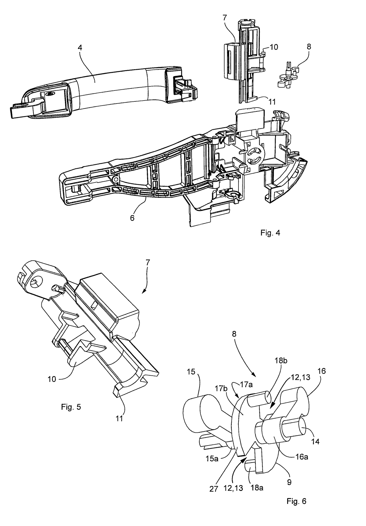
[0016]To keep the installation space of the locking device as small as possible, it is advantageous to pivotally mount a respective first longitudinal end of the lever-arm shaped mass element on a rotational axis, wherein the retaining element is pivotally mounted by means of the rotational axis on the handle support and on the rotational axis between the first mass element and the second mass element. At the same time, the retaining element can be moved and turned in relation to the mass elements, although the retaining element and the two mass elements are mounted on the same rotational axis.
[0018]A further embodiment of the invention provides that the slot-shaped recess formed in the disc-shaped retaining element is designed in the form of a radially extending groove into which the motion projection of the coupling device can pivot. This embodiment makes it possible to keep the installation space intended for the locking device small especially when the coupling device is swivel-mounted about a swivel axis at the handle support, wherein the rotational axis of the retaining element is basically aligned parallel to the swivel axis of the coupling device.
[0020]To prevent the handle form further blockage after accelerating forces have been applied, the invention is advantageously designed in such a way that it provides a mechanical resetting element which has the power to push the retaining element into basic position. Different from commonly known locking devices which lock in the event of a collision as a result of the impact of accelerating forces and which have to be manually released so that the handle can be actuated again, the handle of the invention-based door handle arrangement can be used and actuated even after the impact of accelerating forces because the locking device has returned to its basic position.

Problems solved by technology

Such door handle arrangements with a locking device used as a mass lock are to prevent that the accelerating forces occurring during an accident result in actuating the handle or door handle and inadvertently opening the door of the motor vehicle, which would present considerable risks for a passenger of the vehicle.
In the event of an accident, forces are exerted on the blocking element, and an inadvertent movement of the handle, also resulting from the applied forces, is blocked.
Door handle arrangements known from prior art which have a mass lock or a locking device that does not engage when activated but returns to its basic position involve the danger that, for example, in the event of a lateral collision, alternating accelerating forces occur which result in a fluttering of the door handle arrangement, or a back and forth movement.
Consequently, strong and distinctive vibrations or long-lasting vibrations resulting from an impact of accelerating forces involve the danger that in the case of a back and forth moving or oscillating locking device the displacement range is not long enough to reliably prevent a blockage of the handle or the bell crank.
Furthermore, the well-known door handle arrangements with crash stop have the disadvantage that they are designed only for accelerating forces directed into the interior of the vehicle.

Method used


Image

  • Door handle arrangement for a motor vehicle
  • Door handle arrangement for a motor vehicle
  • Door handle arrangement for a motor vehicle

Examples


Embodiment Construction

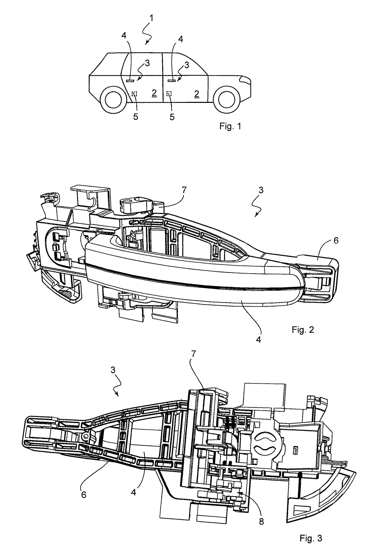
[0042]FIG. 1 shows an exemplary diagram of a vehicle or motor vehicle 1 in the form of an automobile, which has 4 doors 2 which can be opened by means of a door handle arrangement 3 and especially by means of a door handle or handle 4. The doors 2 are locked via respective locking systems 5 and can be opened from the outside only via a respective movement of the handle 4. This movement at the handle 4 can comprise a pulling and / or flapping motion, wherein the respective movement of the handle 4 can be transferred mechanically to the respective locking system 5 at least via a coupling device. By moving the handle 4 the respective locking system 5 and thus the associated door 2 can be opened.

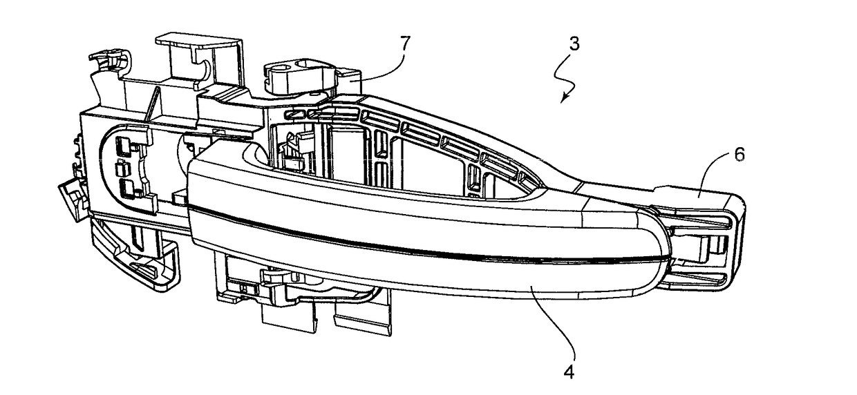
[0043]FIGS. 2, 3 and 4, respectively, show a perspective view of the door handle arrangement 3, wherein a frontal view is shown in FIG. 2, a rear view in FIG. 3 and a single component view in FIG. 4. The door handle arrangement 3 has a frame-like handle support 6 which is used in known fashion to ...


PUM


Abstract

A door handle arrangement for a motor vehicle includes a handle support, a handle, a coupling device, a locking device and a retaining element. When an accelerating force is applied in a first direction, as a result of a motor vehicle accident, the retaining element moves from a basic position in which it is possible to actuate the handle into a direction of blockage in which an actuation of the locking system by the handle and / or the coupling device is blocked. The locking device reliably and securely blocks the handle or the coupling device in the event of a collision. This is achieved in that the retaining element is designed to move from the basic position into the particular direction of blockage when an accelerating force resulting from a motor vehicle accident is applied in a second direction that is opposite of the first direction.

Description

BACKGROUND[0001]The invention relates to a door handle arrangement for a motor vehicle with a frame-like handle support and a manually actuated handle, which is pivotally mounted at the handle support so that a user is able to open a door or flap of the motor vehicle; it further relates to a coupling device that is swivel-mounted at the handle support, by means of which coupling device a movement of the handle can be transferred to an on-board locking system and a locking device with a retaining element, which is movably attached to the handle support and used as a mass lock, wherein the retaining element is designed in such a way that on impact of an accelerating force resulting from a motor vehicle accident it can be moved from a basic position in which the handle can be actuated to a direction of blockage in which the handle and / or the coupling device is impeded from actuating the locking system.[0002]Such door handle arrangements with a locking device used as a mass lock are to ...

Claims


Application Information

Patent Timeline
Patent Type & Authority Patents(United States)
IPC IPC(8): E05B3/00E05B7/00E05B85/16E05B77/06
CPCE05B7/00E05B77/06E05B85/16Y10T292/57
Inventor NIEGELOH, ANDREASBARTELS, MARKUS
Owner HUF HULSBECK & FURST GMBH & CO KG
Learn More