
Media accumulator-ejector for use with an imaging device

a technology of accumulator and media, which is applied in the direction of electrographic process, instruments, transportation and packaging, etc., can solve the problems of reducing throughput speed performance, limited speed point in ejection of media stack, and limited ability for single media sheet feed through feeding,

Active Publication Date: 2017-05-02
LEXMARK INT INC
View PDF6 Cites 2 Cited by
  • Summary
  • Abstract
  • Description
  • Claims
  • Application Information

AI Technical Summary

Benefits of technology

The patent describes a media accumulator-ejector for use with an imaging apparatus. The accumulator-ejector includes an upper roll and a lower roll mounted to a frame. The upper roll has wheels and a linkage, while the lower roll has wheels and a linkage. The upper and lower rolls extend transversely across the accumulation plate. A drive mechanism is included to eject media from the accumulation plate. A lift mechanism is also included to move the upper and lower rolls to engage the media stack and eject it. The accumulator-ejector allows for continuous feeding of individual media sheets from the accumulation plate. The technical effects of the patent are improved media handling and ejection capabilities for the imaging apparatus.

Problems solved by technology

There is a limited speed point in ejection of the media stack.
Also, there is limited capability for single media sheet pass through feeding.
This wastes time and reduces throughput speed performance.
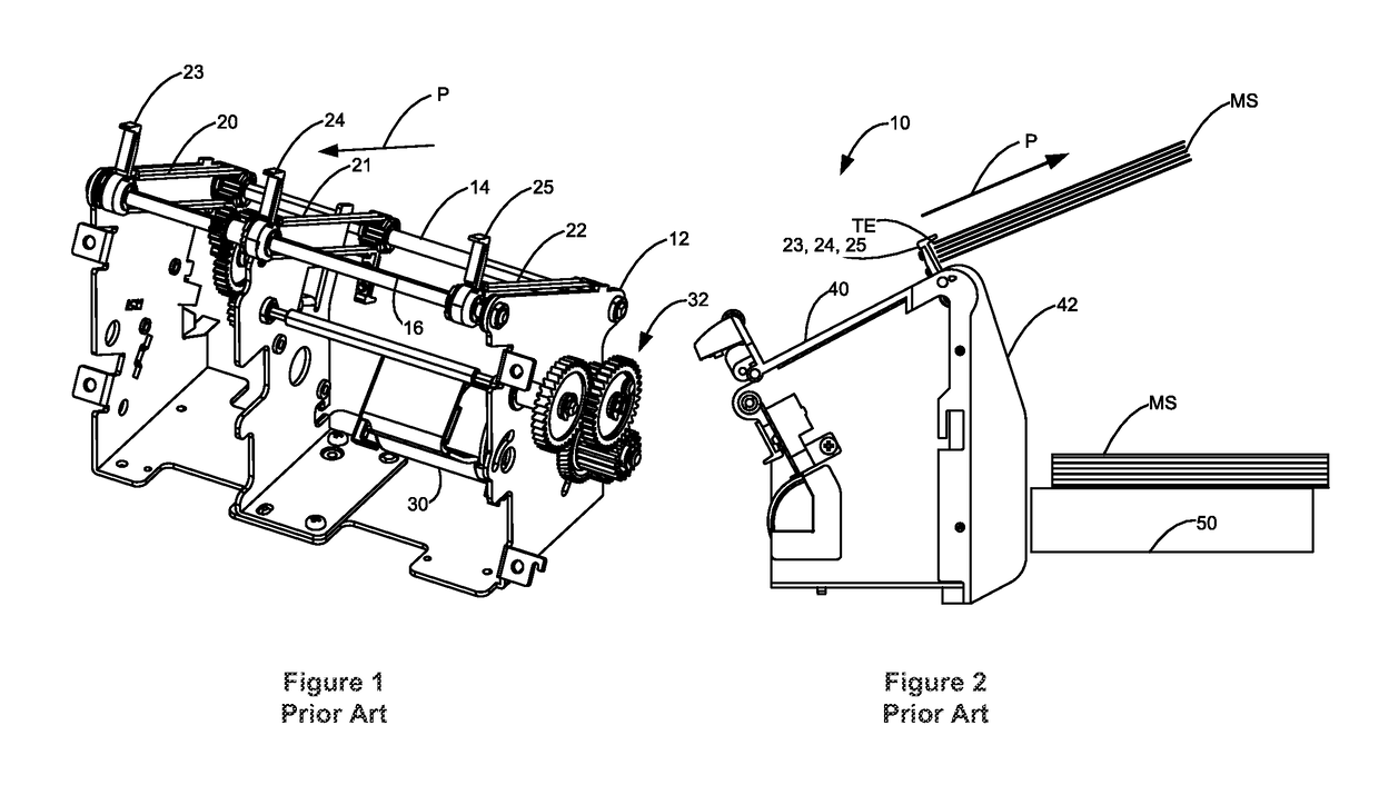
Lastly, there is a manufacturing and service challenge to properly time or align the fingers 23-25 during assembly or after belt replacement.

Method used


Image

  • Media accumulator-ejector for use with an imaging device
  • Media accumulator-ejector for use with an imaging device
  • Media accumulator-ejector for use with an imaging device

Examples


Embodiment Construction

[0029]It is to be understood that the present disclosure is not limited in its application to the details of construction and the arrangement of components set forth in the following description or illustrated in the drawings. The present disclosure is capable of other embodiments and of being practiced or of being carried out in various ways. Also, it is to be understood that the phraseology and terminology used herein is for the purpose of description and should not be regarded as limiting. As used herein, the terms “having”, “containing”, “including”, “comprising”, and the like are open-ended terms that indicate the presence of stated elements or features, but do not preclude additional elements or features. The articles “a”, “an” and “the” are intended to include the plural as well as the singular, unless the context clearly indicates otherwise. The use of “including”, “comprising”, or “having” and variations thereof herein is meant to encompass the items listed thereafter and e...


PUM

PropertyMeasurementUnit
Angleaaaaaaaaaa
Angleaaaaaaaaaa
Flexibilityaaaaaaaaaa

Abstract

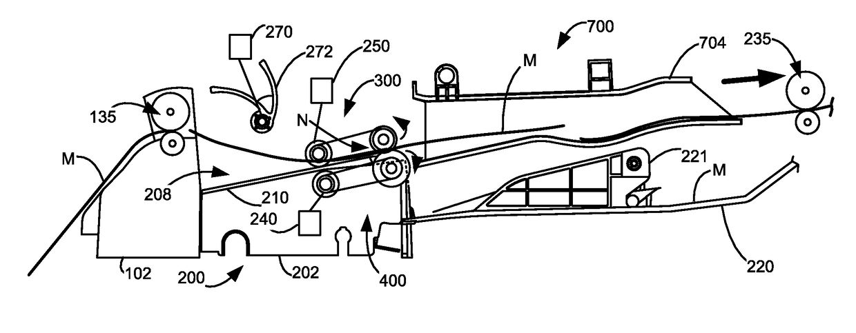
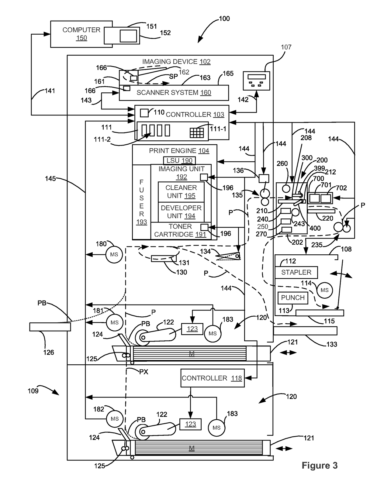
A media accumulator-ejector for use with an imaging apparatus. Rotatable upper and lower roll assemblies are located above and below a media accumulation zone comprised of an accumulation plate and positioned to receive media exiting an imaging device. The roll assemblies are moveable like jaws between an open position where media can accumulate on the accumulation plate without interference with the roll assemblies and a clamping position where the accumulated media is grasped by the upper and lower roll assemblies. The upper and lower roll assemblies are then rotated to eject the accumulated media from the accumulation plate. The upper and lower roll assemblies can also grasp and continuously eject individual sheets of media at a predetermined process speed.

Description

CROSS REFERENCES TO RELATED APPLICATIONS[0001]None.STATEMENT REGARDING FEDERALLY SPONSORED RESEARCH OR DEVELOPMENT[0002]None.REFERENCE TO SEQUENTIAL LISTING, ETC.[0003]None.BACKGROUND[0004]Field of the Disclosure[0005]The present disclosure relates generally to imaging devices and finishers, and more particularly to those having media accumulator-ejector.[0006]Description of the Related Art[0007]Stapler finishing devices have long been using a rubber finger, belt drive media accumulator-ejector devices. As shown in FIGS. 1 and 2, the prior art media accumulator-ejector 10 is typically made up of a frame 12 having mounted thereon two parallel, rotatable shafts 14, 16, positioned transverse to a media path P. Three belts 20, 21, 22 are mounted to the shafts 14, 16 and driven by a motor 30 via a gear train 32 and rotate parallel to media path P. Attached to the belts 20-22 are respective aligned, outwardly protruding rubber fingers 23-25, that extend out through slots provided in a med...

Claims


Application Information

Patent Timeline
IPC IPC(8): B65H29/14G03G15/00B65H31/34B65H29/12B65H31/30
CPCG03G15/6552B65H31/34B65H29/12B65H31/3027B65H29/14B65H29/145B65H29/125B65H2404/1441B65H2404/144B65H29/70B65H31/3018B65H31/36B65H31/38G03G15/6544B65H2301/4212B65H2301/4213B65H2301/5122B65H2404/1114B65H2404/1442B65H2404/1521B65H2801/27G03G2215/00818G03G2215/00827B65H31/02
Inventor CEDENO, MENELEO DE CASTROBOGGS, AARON JACOBCHAVEZ, JOSE JONNA TOHAYCHEN, JIEFAMADOR, GERALD CONCEJOSHENSLEY, GREGORY MICHAELKEKIM, KIM MATACINOSSPITZ, DONALD NORMAN
Owner LEXMARK INT INC
Learn More