
Photoelectric conversion device and photoelectric conversion module

A conversion device, optoelectronic technology, applied in photovoltaic power generation, circuits, electrical components, etc., can solve the problems of reduced charge amount, reduced carrier density, unable to improve photoelectric conversion efficiency, etc., to improve short-circuit current density and high collection capacity. Effect

Inactive Publication Date: 2018-11-06
KYOCERA CORP
View PDF7 Cites 0 Cited by
  • Summary
  • Abstract
  • Description
  • Claims
  • Application Information

AI Technical Summary

Problems solved by technology

[0006] However, when quantum dots are aggregated to form a quantum dot accumulation part, the carriers generated in the quantum dots are easily combined with defects existing in the quantum dot accumulation part including the barrier layer and annihilated. The density of the flow will decrease, which will cause a decrease in the amount of charge, and there is a problem that the photoelectric conversion efficiency cannot be improved.

Method used


Image

  • Photoelectric conversion device and photoelectric conversion module
  • Photoelectric conversion device and photoelectric conversion module
  • Photoelectric conversion device and photoelectric conversion module

Examples


Embodiment

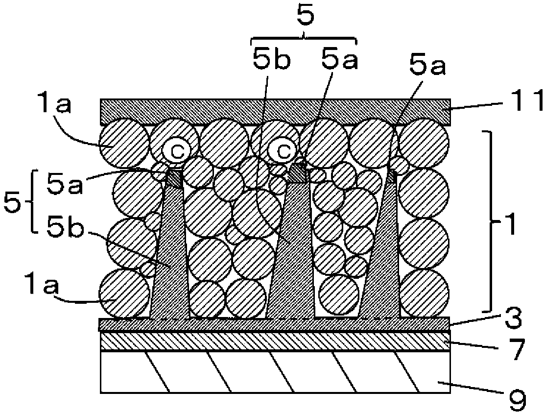
[0074] Hereinafter, an example in which a photoelectric conversion device (quantum dot solar cell) to which zinc oxide is applied as a main component of the base layer 3 and the carrier collection part 5 is produced and evaluated is shown.

[0075] First, a glass substrate on which an ITO film was formed was prepared. Next, a mixed solution of zinc nitrate (500mM (mmol)) and hexamethylenetetramine (250mM (mmol)) was prepared, and the stirring conditions were changed to 0 minutes, 20 minutes, and 40 minutes, thereby forming on the ITO film. Base layer 3 and carrier collection part 5 having different molar ratios of oxygen to metal (zinc).

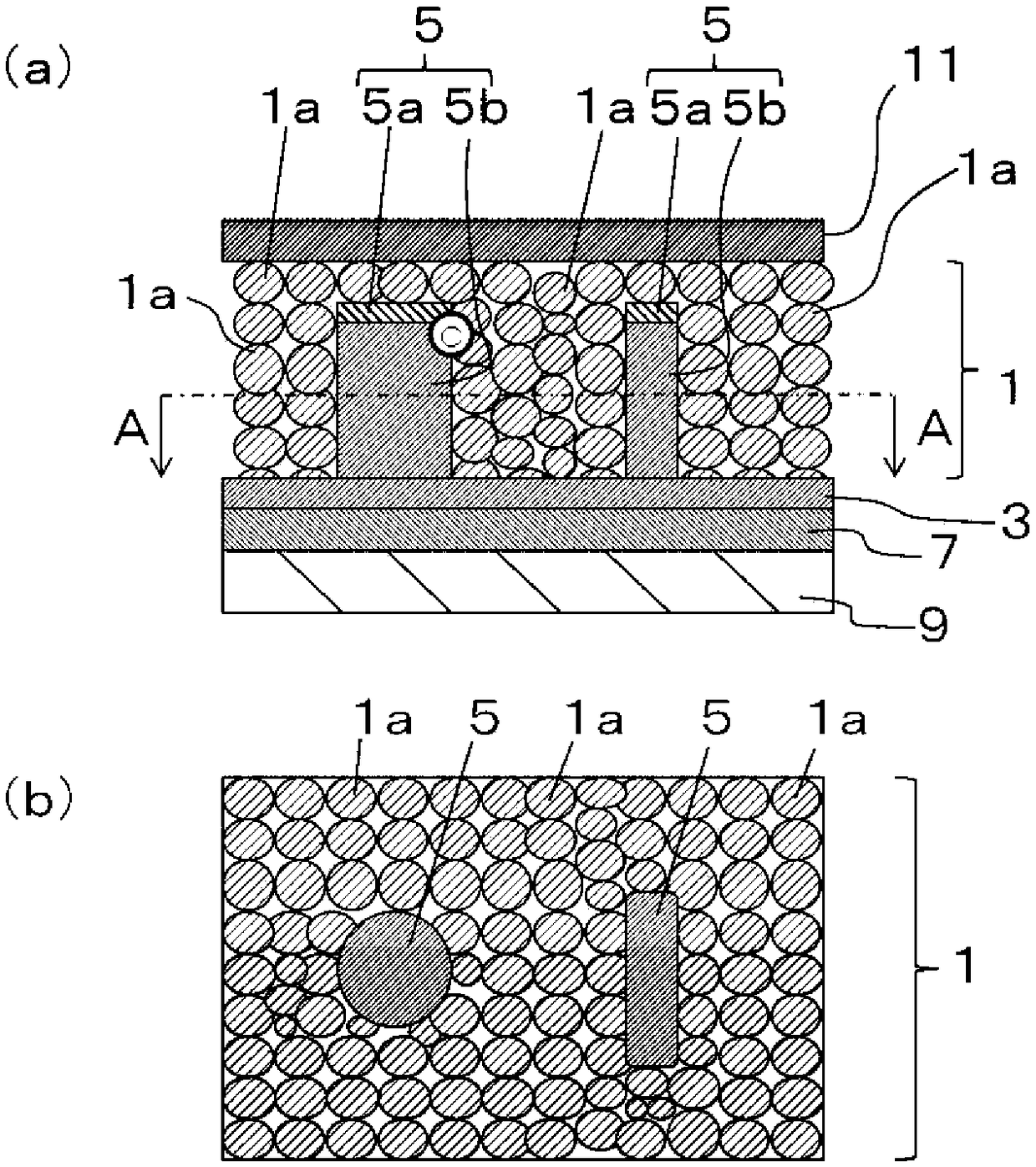
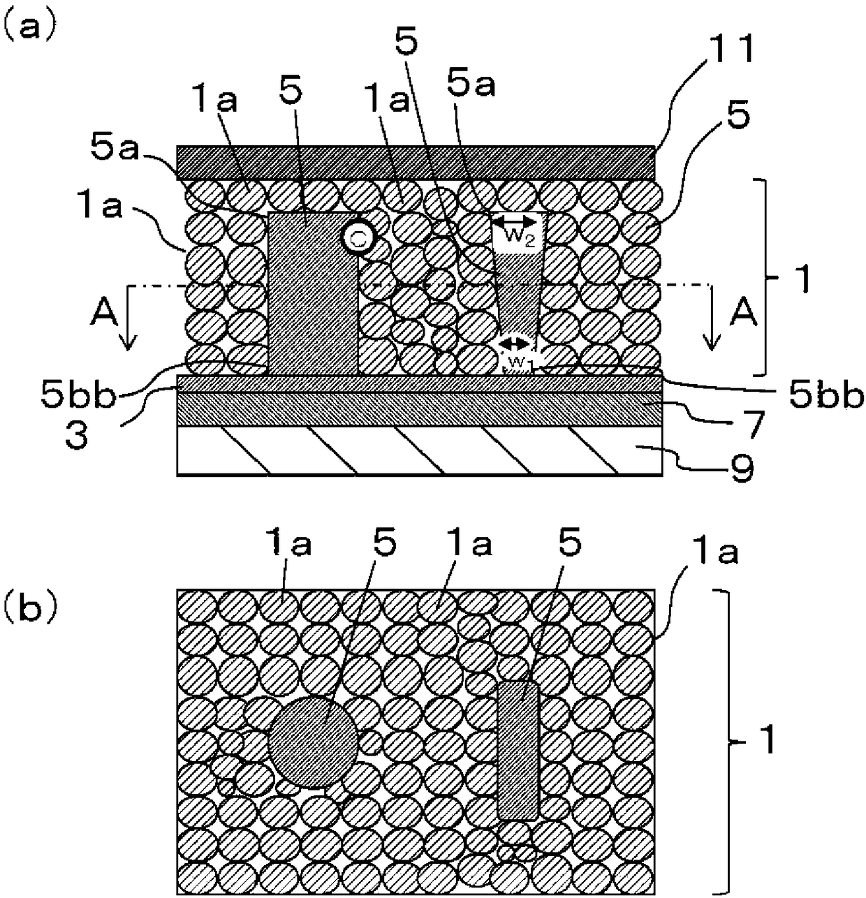
[0076] Next, a previously prepared solution containing PbS quantum dots (average particle diameter: 5 nm) was applied by spin coating from above the carrier collection portion 5, followed by densification treatment to form the quantum dot accumulation portion 1.

[0077] Next, on the surface of the quantum dot accumulation part 1, a vapor-d...


PUM


Abstract

The photoelectric conversion device includes a quantum dot accumulation zone, a base layer having current collecting properties which is disposed on at least one major surface of the quantum dot accumulation zone, and a plurality of columnar carrier collection zones, each extending from the base layer into the quantum dot accumulation zone and having an open end. Each of the carrier collection zones is composed mainly of metal oxide. An open end part has a higher mole ratio of oxygen to metal than a body part other than the open end part.

Description

technical field [0001] The invention relates to a photoelectric conversion device and a photoelectric conversion module. Background technique [0002] In solar cells equipped with quantum dots (hereinafter, sometimes referred to as "quantum dot solar cells") that are expected as next-generation photoelectric conversion devices, between two semiconductor layers forming a pn junction is used as a photosensitive layer. And the quantum dot accumulation part in which quantum dots are accumulated is inserted. [0003] In the quantum dot solar cell, electrons excited by irradiating the quantum dots with sunlight of a specific wavelength and holes generated when the electrons are excited from the valence band to the conduction band are used as carriers. [0004] In this case, the photoelectric conversion efficiency of the quantum dot solar cell is related to the total amount of carriers generated in the quantum dot gathering part, therefore, for example, the thickness of the quantu...

Claims


Application Information

Patent Timeline
Patent Type & Authority Patents(China)
IPC IPC(8): H01L31/0352B82Y20/00H01L31/0224H01L31/0236
CPCB82Y20/00B82Y30/00C01G9/02C01P2002/85H01L31/022425H01L31/035218H01L31/03529H01L31/0224H01L31/0236H01L31/0352Y02E10/50Y10S977/774Y10S977/948H01L31/02963H01L31/05H01L31/0725
Inventor 二宫寿一久保新太郎仲山彻
Owner KYOCERA CORP
Learn More