Thoracic aorta stent graft

a stent and aorta technology, applied in the field of stent grafts and stent grafts, can solve the problems of difficult access to fenestrations through corresponding vessels, such as the brachiocephalic and the left brachial arteries, and achieve the effect of improving the fenestration efficiency and reducing the difficulty of grafting

Active Publication Date: 2017-05-16
COOK MEDICAL TECH LLC
View PDF29 Cites 21 Cited by
  • Summary
  • Abstract
  • Description
  • Claims
  • Application Information

AI Technical Summary

Benefits of technology

[0023]It will be seen that by this invention there is provided a stent graft for placement in the thoracic arch of a patient. The stent graft can be placed such that the intermediate portion is just proximal of the brachiocephalic artery and on the outside of the curve of the thoracic arch. By this placement there is defined, by the difference in diameter of the first and second portions, an open region outside the stent graft distal of the aperture in the step portion, so that blood flow can occur through the aperture to the open region enabling circulation to be preserved to the major vessels through the internal branches during the progress of an operation. As the intermediate portion is of stent graft is of a lesser diameter there is provided a working space in the recess in which a guide wire from the branch arteries can be directed to enter the internal tube to enable catheterisation. Subsequently a side branch stent graft can be deployed from the respective branch artery into the tube to provide blood flow into that branch artery.

Problems solved by technology

If a stent graft has been deployed into the thoracic aorta around the arch such that its fenestrations are not aligned precisely with their corresponding great vessels of the arch, then it can be difficult to access the fenestrations through corresponding vessels (such as the brachiocephalic and the left brachial arteries).

Method used


Image

  • Thoracic aorta stent graft
  • Thoracic aorta stent graft
  • Thoracic aorta stent graft

Examples


Embodiment Construction

Or Mode(s) / if Applicable

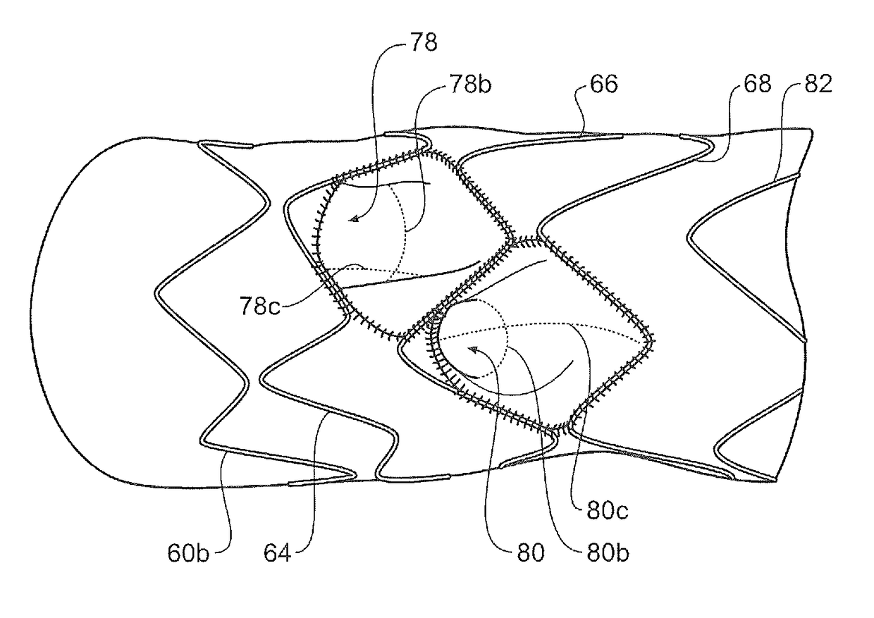
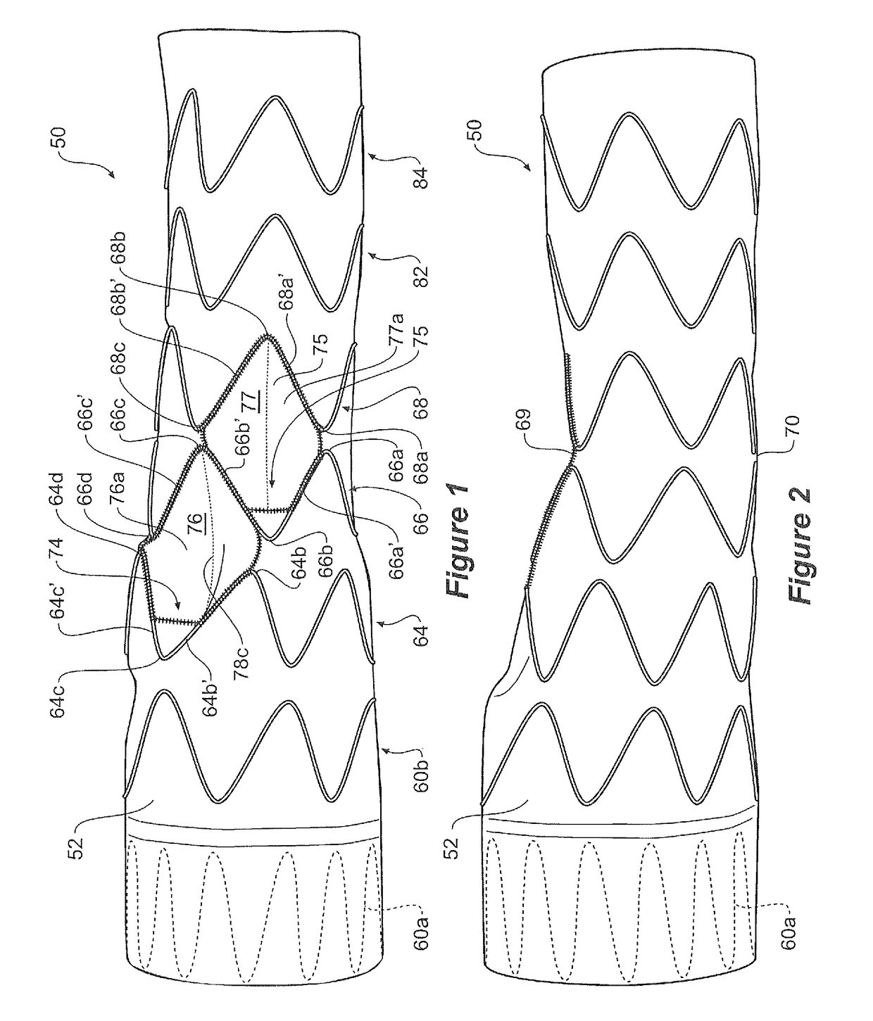
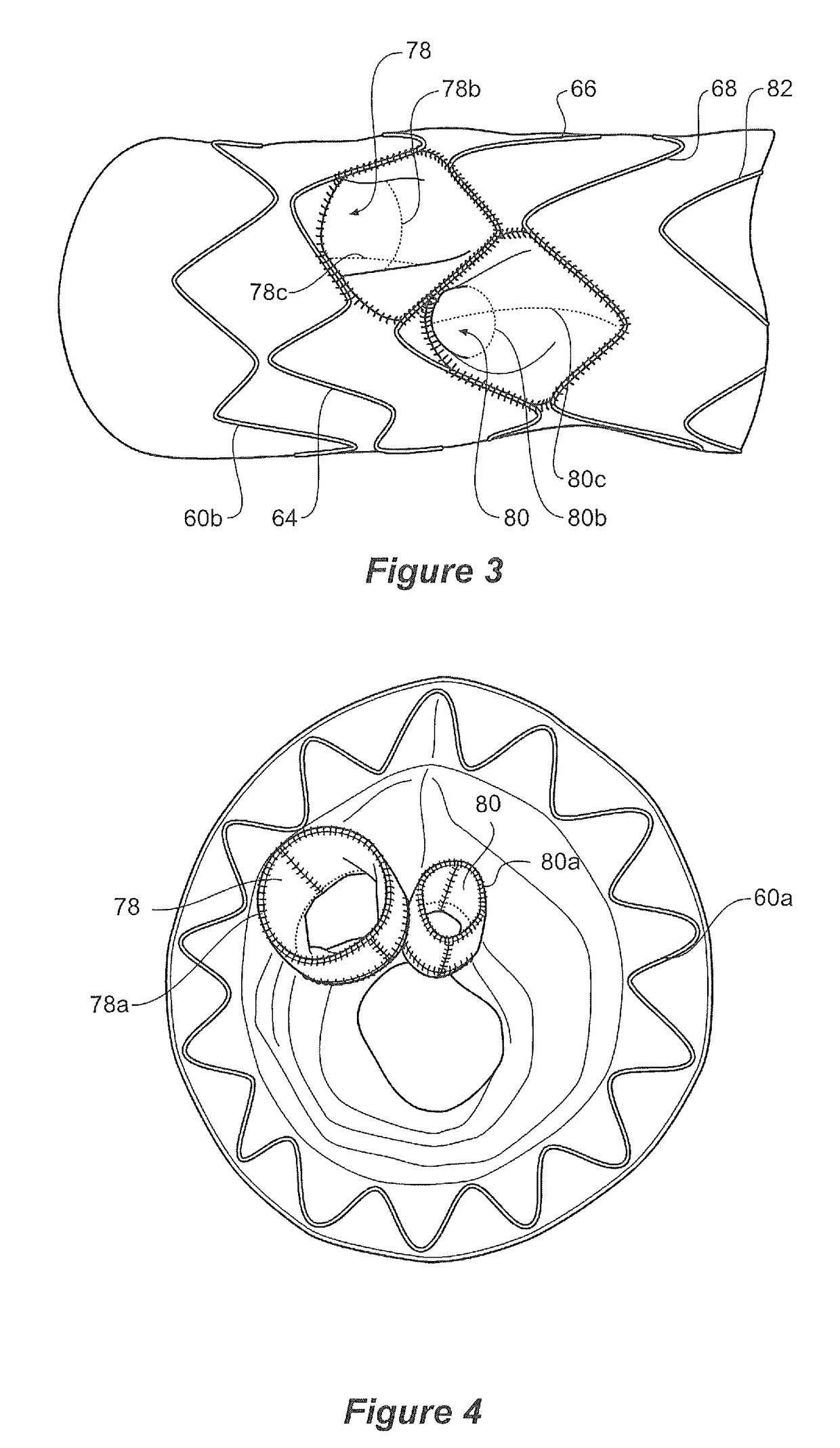
[0059]FIGS. 1 to 6 show an embodiment of stent graft according to the present invention. In this embodiment the tubular body 52 of this embodiment of stent graft 50 comprises a proximal portion 54, an intermediate portion 56 and a distal portion 58 as shown in FIG. 5.

[0060]Referring to FIG. 1 it can be seen that the proximal portion 54 comprises a tubular body of a biocompatible graft material and is supported by self expanding zig zag stents 60a and 60b. The stent 60a is internal to provide a smooth sealing surface to engage against the wall of the ascending aorta, and the stent 60b is external. The proximal portion may have a diameter from 35 to 50 mm.

[0061]The distal portion 58 is again formed from a tubular body of a biocompatible graft material and is supported by self expanding zig zag stents 82 and 84. The distal portion 58 can have a diameter in the range of from 30 to 40 mm.

[0062]The intermediate portion 56 is supported by self expanding zig zag sten...


PUM


Abstract

A stent graft for placement in the thoracic arch of a patient has a tubular body defining a main lumen therethrough, a plurality of zig zag stents along the tubular body, each of the stents comprising a plurality of struts and bends, the bends being between adjacent struts. At least a first stent and an adjacent second stent having at least a pair of adjacent bends on the first stent aligned with an adjacent pair of bends on the second stent, whereby a first pair of adjacent struts of the first stent and a second pair of adjacent struts of the second adjacent stent together define a diamond shape region. A recess is within the diamond shaped region with the recess extending into the lumen of the tubular body. A fenestration extending into the tubular body within the recess in the diamond shaped region and a graft tube leading from the fenestration into the main lumen. There can be one, two or three diamond shaped regions, recesses, fenestrations and graft tubes Proximally of the or each diamond shaped region the tubular body has a first diameter, distally of the diamond shaped region the tubular body has a second diameter and in the region of the tubular body around the diamond shaped region the tubular body has a third diameter, the first diameter being greater than the second diameter and both the first and second diameter being greater than the third diameter whereby a central region is defined which will allow circumferential blood flow during an operation out of the graft tube into the recess and then into the central region.

Description

CROSS REFERENCE TO RELATED APPLICATION[0001]This application is a National Stage of International Application PCT / US2011 / 024148, filed Feb. 9, 2011, which claims priority to U.S. Provisional Application Ser. No. 61 / 302,586, filed Feb. 9, 2010. The entire contents of both of these applications are hereby incorporated by reference into this disclosure.TECHNICAL FIELD[0002]This invention relates to a medical device for treatment of aortic arch disease and more particularly to a stent graft for deployment into the thoracic aorta of a patient for that purpose.BACKGROUND ART[0003]In recent years endovascular implantable devices have been developed for treatment of aortic aneurysms. These devices are delivered to the treatment site through the vascular system of the patient rather than by open surgery. The devices include a tubular or cylindrical framework or scaffolding of one or more stents to which is secured a tubular shape of graft material such as woven Dacron, polyester polytetraflu...

Claims


Application Information

Patent Timeline
Patent Type & Authority Patents(United States)
IPC IPC(8): A61F2/07A61F2/06A61F2/89A61F2/915
CPCA61F2/07A61F2/89A61F2/915A61F2002/061A61F2002/075A61F2210/0014A61F2/856A61F2/954A61F2002/826A61F2250/0039
Inventor HARTLEY, DAVID ERNEST
Owner COOK MEDICAL TECH LLC
Why Eureka
Try Eureka