
Stability of gas atomized reactive powders through multiple step in-situ passivation

a technology of reactive powders and gas atomization, which is applied in the direction of metal-working apparatuses, explosives, transportation and packaging, etc., can solve the problems of pyrophoric powders, achieve the effects of improving the thermal ignition temperature and spark ignition resistance of atomized particles, improving ignition stability, and being more resistant to ignition

Active Publication Date: 2017-05-16
IOWA STATE UNIV RES FOUND
View PDF9 Cites 3 Cited by
  • Summary
  • Abstract
  • Description
  • Claims
  • Application Information

AI Technical Summary

Benefits of technology

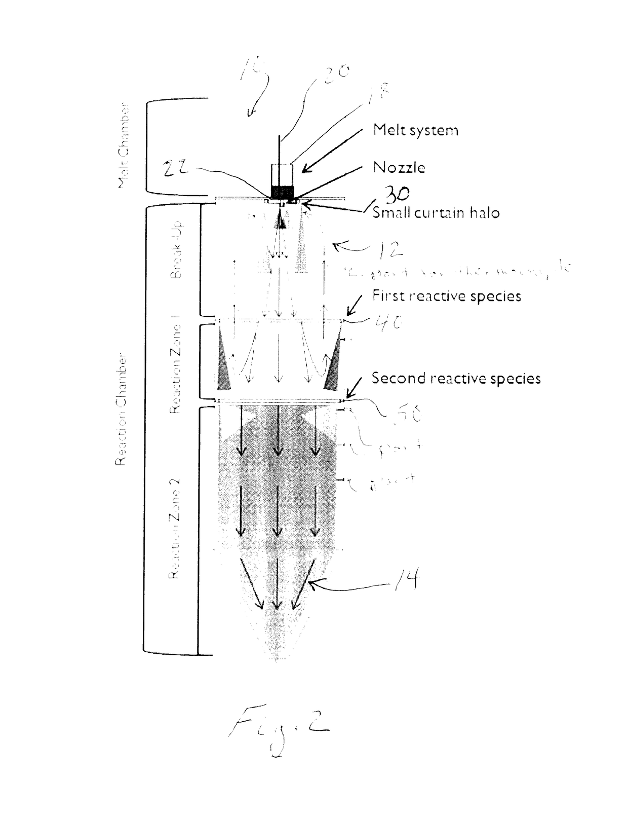
The present invention is about gas atomization of reactive metals and alloys. It involves exposing atomized particles to multiple gaseous reactive agents to form a protective reaction film on the particles. This is especially useful for making highly pyrophoric reactive metal or alloy atomized powders. The gaseous reactive species are introduced into the atomization spray chamber and can include oxygen or a halogen-containing gas like fluorine. The resulting powders have a thin protective layer that includes a reaction product of the metal and the first reactive species, which also includes an amount of the second reactive species to improve ignition stability. The protective layer is formed on the particles to a thickness of only ten's of nanometers and imparts beneficial improved resistance to ignition and humidity. The invention also calls for controlling the particle size and surface area to particle volume ratio of the particles to further reduce the risk of ignition.

Problems solved by technology

However, these powders are pyrophoric and must be handled carefully and kept dry at all times.
Similar reactivity issues affect the magnesium die-casting industry which has lead to extensive research on methods of protecting magnesium from spontaneous ignition during melting operations and suppressing magnesium vaporization resulting from the metal's extremely high vapor pressure.

Method used


Image

  • Stability of gas atomized reactive powders through multiple step in-situ passivation
  • Stability of gas atomized reactive powders through multiple step in-situ passivation
  • Stability of gas atomized reactive powders through multiple step in-situ passivation

Examples


example

[0022]The following Example for making magnesium powder is offered to further illustrate but not limit the present invention:

Experimental Procedure

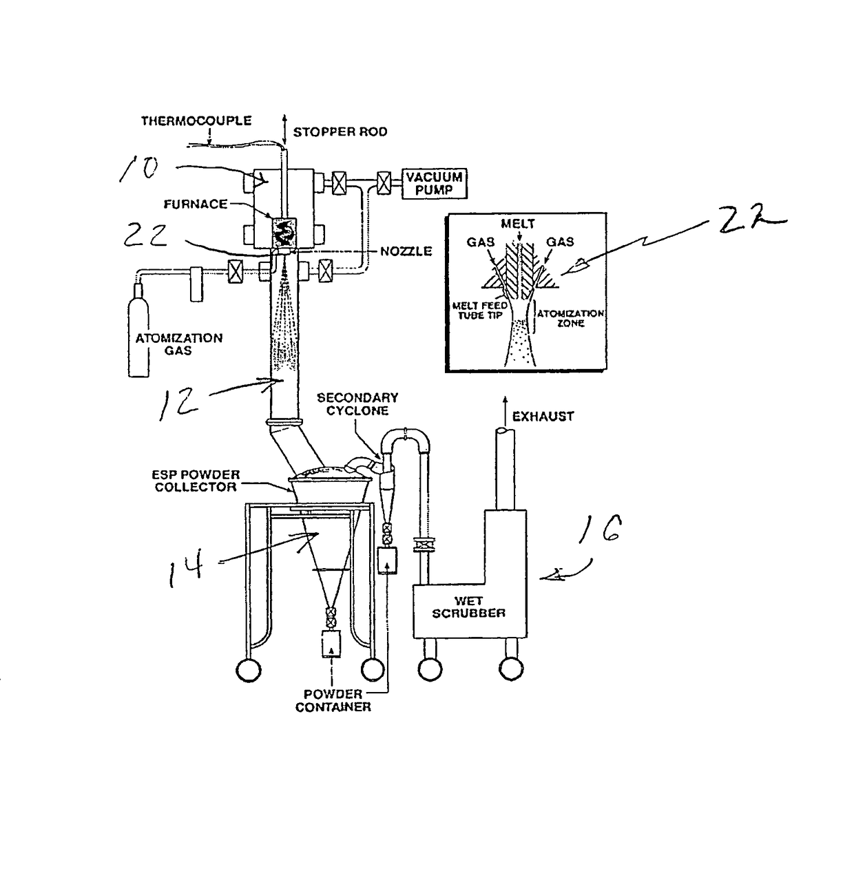
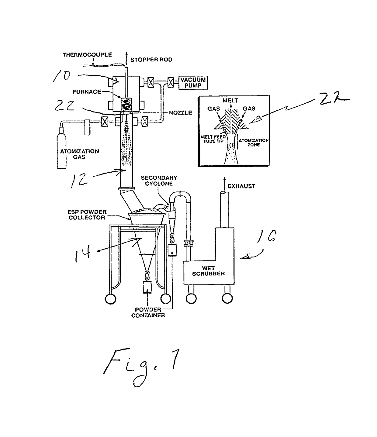
[0023]A modified high pressure gas atomization system (HPGA) located at the Ames laboratory, Ames, Iowa, was used for conducting low pressure gas atomization (LPGA) of magnesium to produce passivated magnesium powders in accordance with an illustrative embodiment of the present invention. The gas atomization system is generally as described in U.S. Pat. Nos. 5,372,629; 5,589,199; and 5,811,187, which are incorporated herein by reference and is shown schematically in FIG. 1. The basic gas atomization system includes a melting chamber 10, a drop tube (spray chamber) 12 beneath the melting chamber and which was 2 feet in diameter and approximately 9 feet tall, and a powder collection chamber 14 along with an exhaust cleaning system 16. The melting chamber 10 on top of the spray chamber 12 contained the melt system. The melt system included a...


PUM

PropertyMeasurementUnit
diameteraaaaaaaaaa
diameteraaaaaaaaaa
diameteraaaaaaaaaa

Abstract

A method for gas atomization of oxygen-reactive reactive metals and alloys wherein the atomized particles are exposed as they solidify and cool in a very short time to multiple gaseous reactive agents for the in-situ formation of a protective reaction film on the atomized particles. The present invention is especially useful for making highly pyrophoric reactive metal or alloy atomized powders, such as atomized magnesium and magnesium alloy powders. The gaseous reactive species (agents) are introduced into the atomization spray chamber at locations downstream of a gas atomizing nozzle as determined by the desired powder or particle temperature for the reactions and the desired thickness of the reaction film.

Description

RELATED APPLICATION[0001]This application claims benefit and priority of U.S. provisional application Ser. No. 61 / 686,822 filed Apr. 12, 2012, the entire disclosure of which is incorporated herein by reference.CONTRACTUAL ORIGIN OF THE INVENTION[0002]The United States Government has rights in this invention pursuant to Contract No. DE-AC02-07CH11358 between the U.S. Department of Energy and Iowa State University.FIELD OF THE INVENTION[0003]The present invention relates to gas atomization of reactive metals and alloys, including and especially magnesium and magnesium alloys, using multiple gaseous reactive agents for the formation of a protective reaction film or layer on gas atomized powders in a manner to increase powder stability, such as increase powder thermal ignition temperature as well as reduce spontaneous discharge by spark ignition.BACKGROUND OF THE INVENTION[0004]Magnesium powder is a critical component in a wide variety of applications. Magnesium powders have application...

Claims


Application Information

Patent Timeline
Patent Type & Authority Patents(United States)
IPC IPC(8): C06B45/00B22F9/16C06B45/30C06B27/00B22F1/00B22F9/08B22F1/145
CPCC06B45/30B22F1/0088B22F9/082B22F9/16B22F2009/0844B22F2999/00B22F2201/03B22F2201/00B22F2201/10B22F1/145
Inventor ANDERSON, IVER E.STEINMETZ, ANDREW D.BYRD, DAVID J.
Owner IOWA STATE UNIV RES FOUND
Learn More