Light source device and projector
a light source device and projector technology, applied in the direction of projectors, semiconductor devices, instruments, etc., can solve the problems of insufficient improvement effect of fluorescence efficiency, failure to be used as illumination light, and confined remaining components of the device, so as to improve fluorescence efficiency and improve projection image brightness.
- Summary
- Abstract
- Description
- Claims
- Application Information
AI Technical Summary
Benefits of technology
Problems solved by technology
Method used
Image
Examples
first embodiment
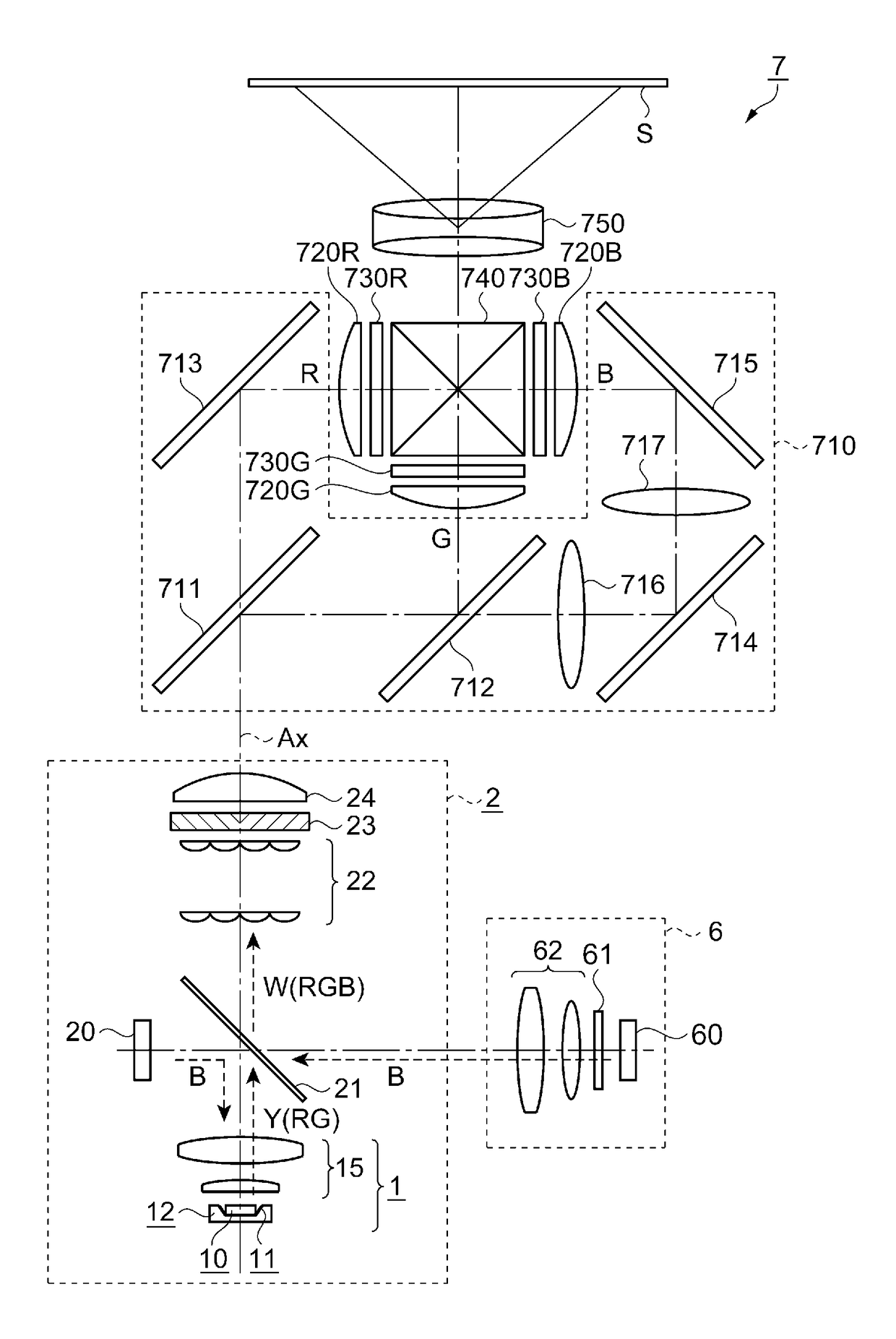
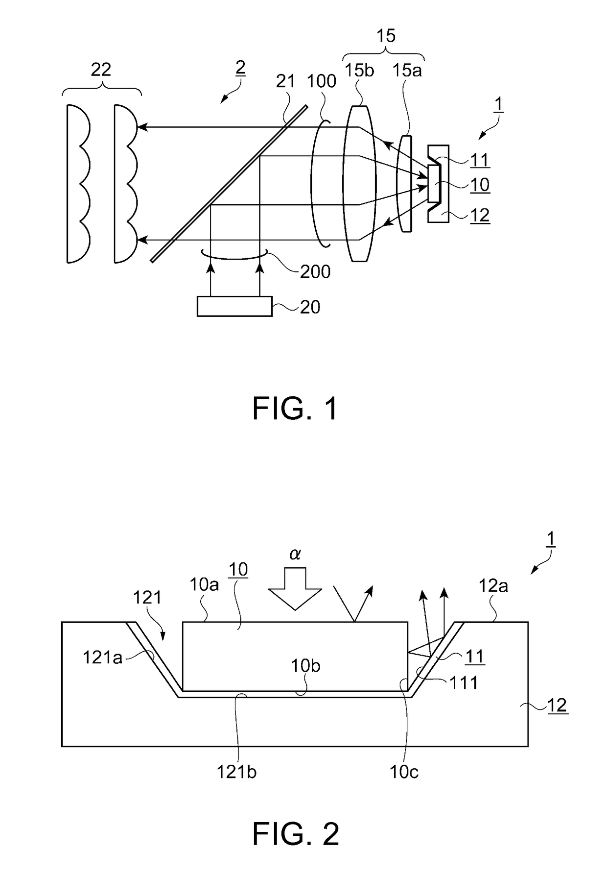
[0040]FIG. 1 is a schematic configuration diagram showing an illumination device 2 using a light source device 1 according to a first embodiment. The configuration of the illumination device 2 (the light source device 1) will be explained with reference to FIG. 1.
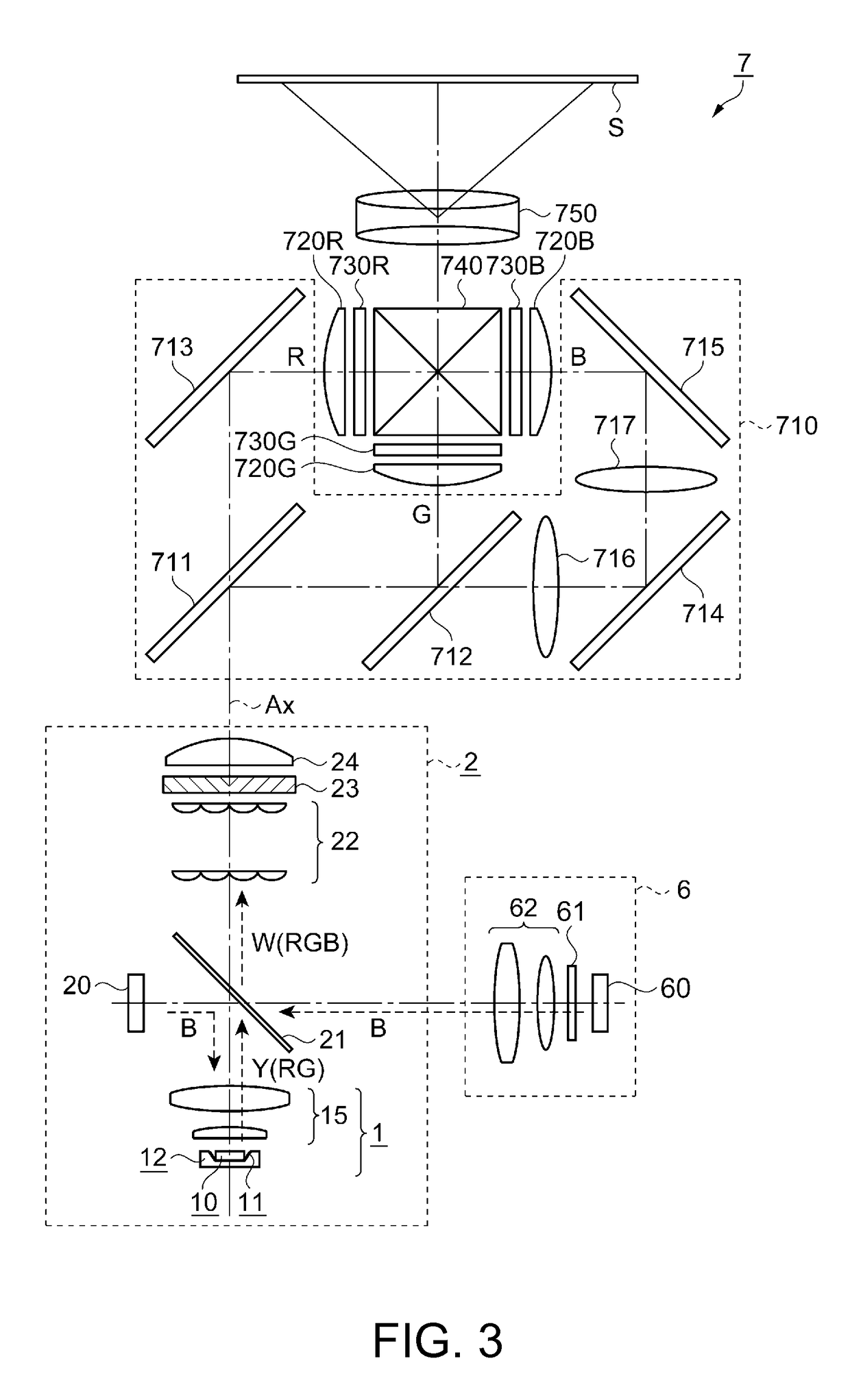
[0041]As shown in FIG. 1, the light source device 1 is provided with a phosphor layer 10, a reflecting member 11, a substrate 12, and a collimating optical system 15. Further, the illumination device 2 is provided with an excitation light source 20, a dichroic mirror 21, a lens array 22, and so on in addition to the light source device 1.
[0042]The phosphor layer 10 generates and then emits the fluorescence in response to irradiation with the excitation light. It should be noted that the details of the phosphor layer 10 will be described later.
[0043]The excitation light source 20 irradiates the phosphor layer 10 with the excitation light. As the excitation light source 20, a laser source for emitting blue light (having a wav...
second embodiment
[0084]FIG. 4 is a cross-sectional view showing a configuration of a light source device 1A according to a second embodiment. The configuration and an operation of the light source device 1A will be explained with reference to FIG. 4.
[0085]As shown in FIG. 4, the light source device 1A according to the present embodiment is different in the cross-sectional shape of the reflecting member from the light source device 1 according to the first embodiment. The rest of the configuration is substantially the same as that of the first embodiment. Therefore, the constituents substantially the same as those of the first embodiment will be denoted with the same reference symbols as in the first embodiment, and the explanation thereof will be omitted.
[0086]In order to improve the usage efficiency of the light, which has been emitted from the light source device, in the optical system in the posterior stage, it is preferable to make the light emitting area small. To that end, it is possible to de...
third embodiment
[0091]FIGS. 5A and 5B are cross-sectional views showing a configuration of a light source device 1B according to the third embodiment of the invention, wherein FIG. 5A is a cross-sectional view, and FIG. 5B is an enlarged view of the cross-sectional view. The configuration and an operation of the light source device 1B will be explained with reference to FIGS. 5A and 5B.
[0092]As shown in FIGS. 5A and 5B, the light source device 1B according to the present embodiment is different from the light source device 1 according to the first embodiment in that alight transmissive member 13 higher in refractive index than air is disposed between the side surface 10c of the phosphor layer 10 and the reflecting member 11. The rest of the configuration is substantially the same as that of the first embodiment. Therefore, the constituents substantially the same as those of the first embodiment will be denoted with the same reference symbols as in the first embodiment, and the explanation thereof w...
PUM
 Abstract
Description
Claims
Application Information
 - R&D
- Intellectual Property
- Life Sciences
- Materials
- Tech Scout
- Unparalleled Data Quality
- Higher Quality Content
- 60% Fewer Hallucinations
Browse by: Latest US Patents, China's latest patents, Technical Efficacy Thesaurus, Application Domain, Technology Topic, Popular Technical Reports.
© 2025 PatSnap. All rights reserved.Legal|Privacy policy|Modern Slavery Act Transparency Statement|Sitemap|About US| Contact US: help@patsnap.com


