Touch panel

a technology of touch panel and display image, applied in the field of touch panel, can solve the problems of degrading brightness and quality of display image, affecting alignment precision, etc., and achieve the effect of enhancing alignment precision and reducing thickness

Inactive Publication Date: 2017-05-16
ILI TECHNOLOGY CORPORATION
View PDF4 Cites 0 Cited by
  • Summary
  • Abstract
  • Description
  • Claims
  • Application Information

AI Technical Summary

Benefits of technology

[0006]It is a primary object of the present invention to provide a touch panel for enhancing alignment precision and reducing thickness.
[0008]In addition to providing higher precision in relative positions of the electrodes, reduced thickness of the touch panel and enhanced sensitivity of the touch panel or reduced numbers of the conducting lines, by further designing the main bodies of the central electrodes as having wavy contours, the touch panel of the present invention improves the issue that the movement track of a touching object detected by the touch panel does not match the actual movement track of the touching object to further improve the touch quality and accuracy of the touch panel.

Problems solved by technology

As such, in a conventional touch panel, positions of these two conductive layers need to be aligned using an alignment machine during the manufacturing process, hence likely causing an alignment precision issue.
Moreover, when the touch panel is integrated with a display panel, an image of the display panel needs to penetrate through a larger number of conductive layers, leading to degraded brightness and quality of a display image.

Method used


Image

  • Touch panel
  • Touch panel
  • Touch panel

Examples


Embodiment Construction

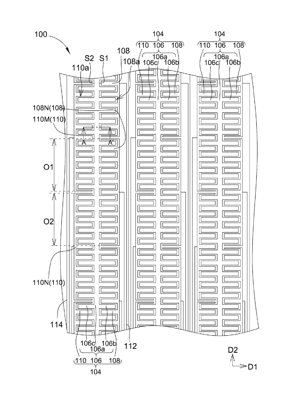
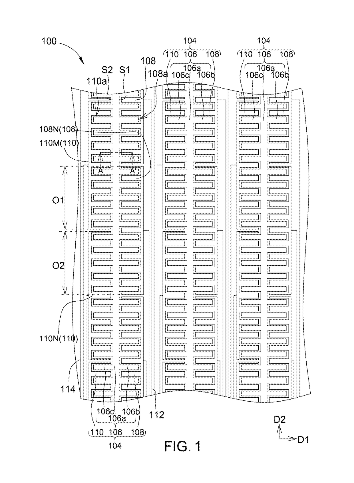
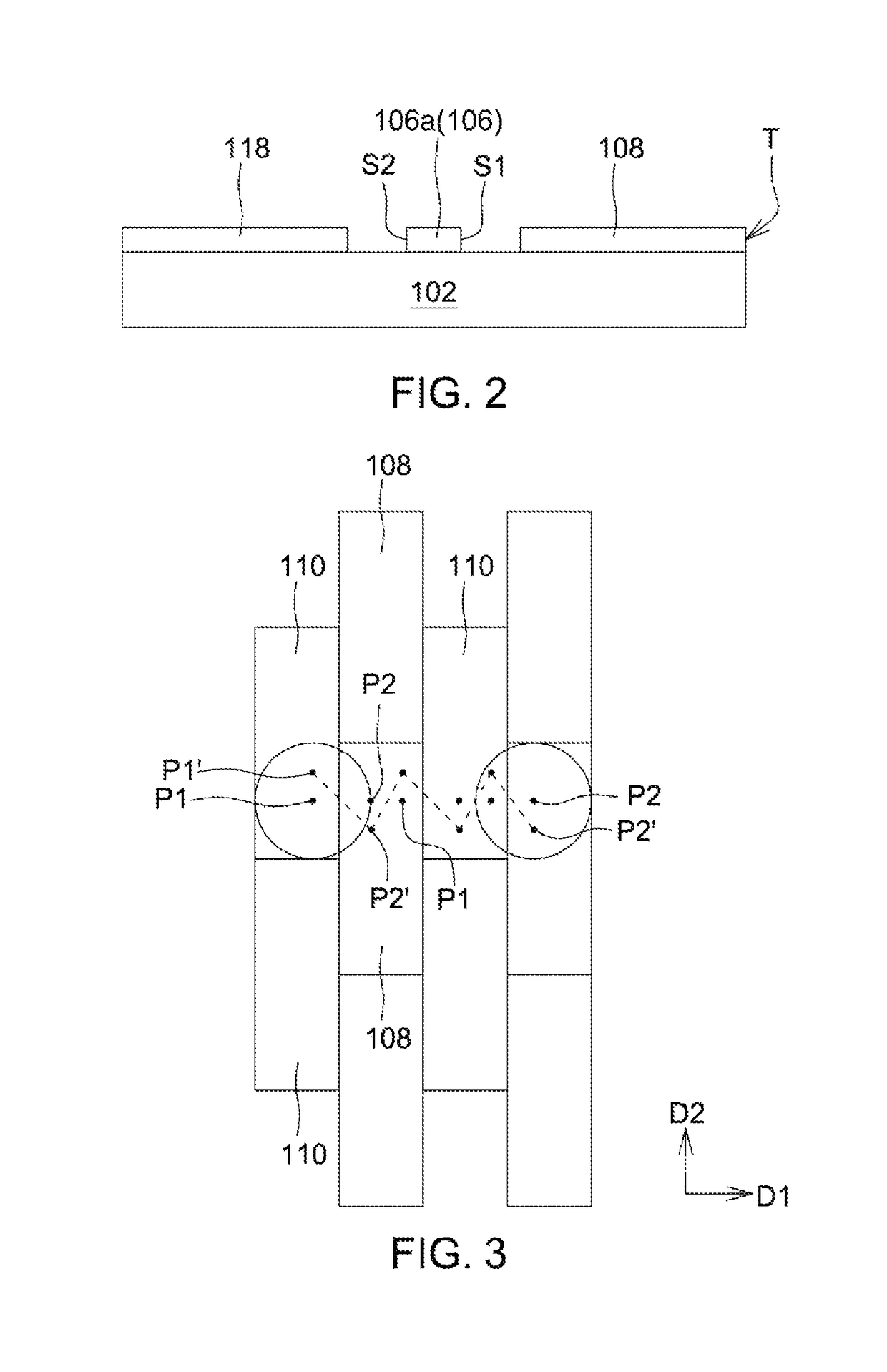
[0018]FIG. 1 shows a top view of a touch panel according to a first embodiment of the present invention. FIG. 2 shows a section view of FIG. 1 along a section line A-A′. As shown in FIG. 1 and FIG. 2, a touch panel 100 includes a substrate 102 and a plurality of touch sensing groups 104. The touch sensing groups 104 are arranged along a first direction D1 on the substrate 102. In the embodiment, for example but not limited to, the substrate 102 may be a transparent substrate, e.g., a glass substrate, a reinforced glass substrate, a quartz substrate, a sapphire substrate or a plastic substrate, or a substrate or panel disposed with elements, e.g., an array substrate, a color filter plate substrate or an organic light emitting diode (OLED) display panel. That is, the touch panel of the present invention may simultaneously serve as a display panel instead of being used solely for touch control. Further, in addition to being disposed outside the display panel, the touch sensing groups o...


PUM


Abstract

A touch panel includes a plurality of touch sensing groups. Each of the touch sensing groups includes a central electrode, a plurality of first electrodes and a plurality of second electrodes. The central electrode includes a main body, and has a wavy contour. The first electrodes and the second electrodes are disposed at two sides of the main body along a direction, respectively. Each of the first electrodes includes a first inner edge adaptively spaced from a first edge of the central electrode. Each of the second electrodes includes a second inner edge adaptively spaced from a second edge of the central electrode. One first electrode of the first electrodes overlaps two adjacent second electrodes of the second electrodes in another direction.

Description

[0001]This application claims the benefit of Taiwan application Serial No. 104125776, filed Aug. 7, 2015, the subject matter of which is incorporated herein by reference.BACKGROUND OF THE INVENTION[0002]Field of the Invention[0003]The invention relates in general to a touch panel, and more particularly to a touch panel that utilizes one single transparent conductive pattern layer to form a touch sensing element.[0004]Description of the Related Art[0005]With the fast progress of technologies, touch panels, featuring human-machine interactions, are extensively applied in electronic products including smart phones, GPS navigator systems, tablet computers and laptop computers. A touch sensing element in a conventional touch panel is formed by a plurality of driving electrodes and a plurality of sensing electrodes that are in a staggered arrangement. To prevent the two from electrical connection, the driving electrodes and the sensing electrodes are respectively formed from two conductiv...

Claims


Application Information

Patent Timeline
Patent Type & Authority Patents(United States)
IPC IPC(8): G06F3/044G06F3/041
CPCG06F3/044G06F3/0412G06F2203/04103G06F3/0443G06F3/0448
Inventor KUO, CHAO-YANGHO, KAI-TING
Owner ILI TECHNOLOGY CORPORATION
Why Eureka
Try Eureka