Alignment apparatus and exposure apparatus

a technology of alignment apparatus and exposure apparatus, which is applied in the direction of photomechanical apparatus, instruments, printing, etc., can solve the problem of inability to perform temperature control by air conditioning, and achieve the effect of reducing the influence of heat generation and increasing the alignment precision

Active Publication Date: 2006-05-30
CANON KK
View PDF15 Cites 2 Cited by
  • Summary
  • Abstract
  • Description
  • Claims
  • Application Information

AI Technical Summary

Benefits of technology

[0008]The present invention has been made in consideration of the above-mentioned problem, and has as its object to eliminate influences of heat generation in a driving unit in a vacuum atmosphere and to increase the alignment precision.

Problems solved by technology

However, an alignment apparatus for use in an EUV or EB exposure apparatus is arranged in a vacuum atmosphere free from heat transfer to a gas, and thus, it is impossible to perform temperature control by air conditioning.

Method used


Image

  • Alignment apparatus and exposure apparatus
  • Alignment apparatus and exposure apparatus
  • Alignment apparatus and exposure apparatus

Examples


first embodiment

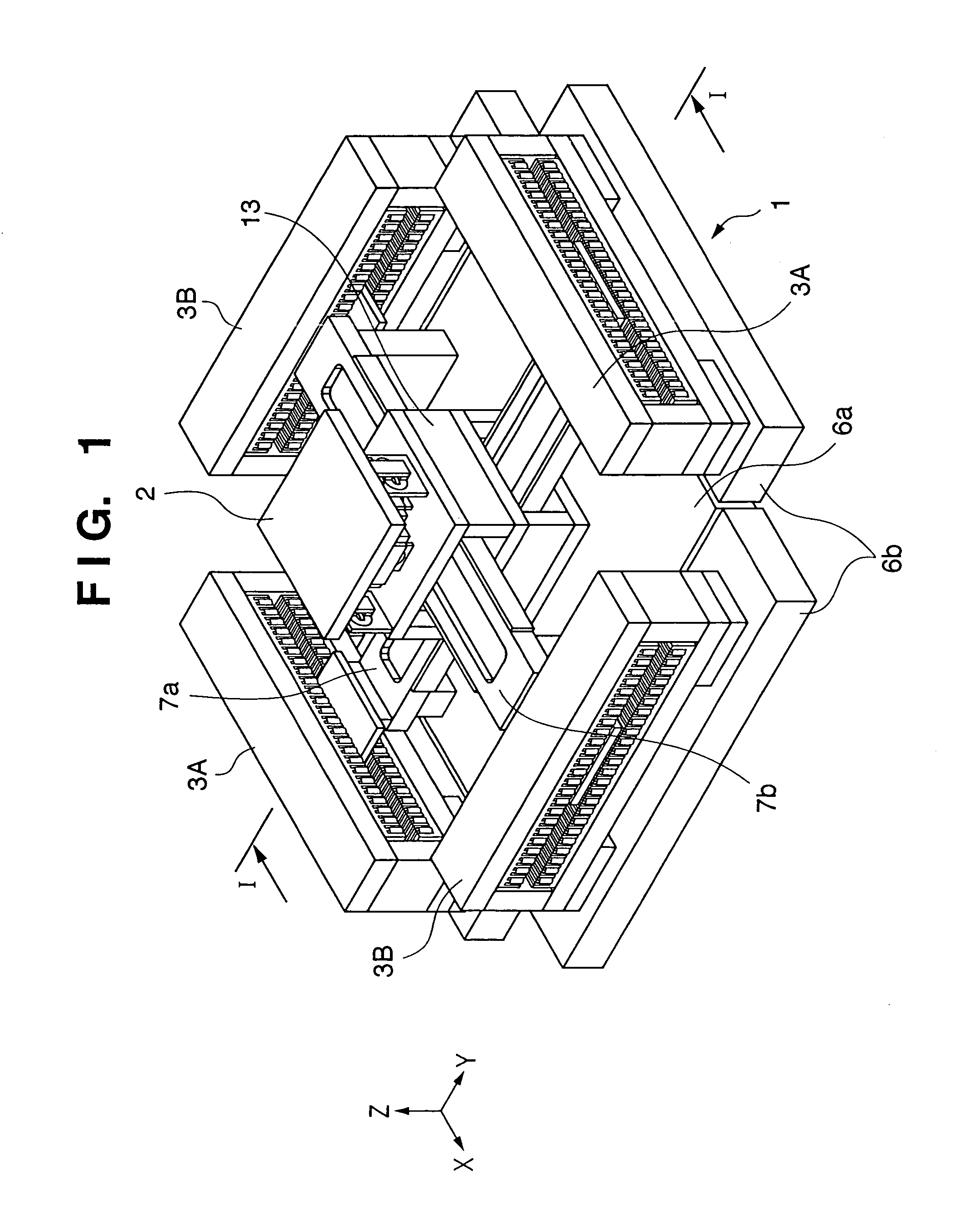
[0033]FIG. 1 is a perspective view showing an alignment apparatus according to the first embodiment of the present invention. FIG. 1 shows an application to a wafer stage mounted in a semiconductor exposure apparatus (to be described later) to align a wafer.

[0034]In FIG. 1, a wafer stage 1 serving as an alignment apparatus comprises a stage base 6a serving as the first support member having a reference surface, which axially supports a slider 13 as an object so as to allow the slider 13 to move in the X- and Y-axis directions, linear motors 3A and 3B serving as driving units, which move the slider 13 in at least one of the X- and Y-axis directions on the reference surface of the stage base 6a to align the slider 13 at a predetermined position, and stator bases 6b, which are provided separately from the stage base 6a to support the linear motors 3A and 3B.

[0035]The driving units comprise an X beam 7a and the X linear motors (for coarse adjustment) 3A serving as the first driving unit...

second embodiment

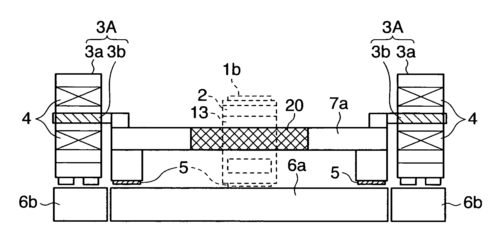
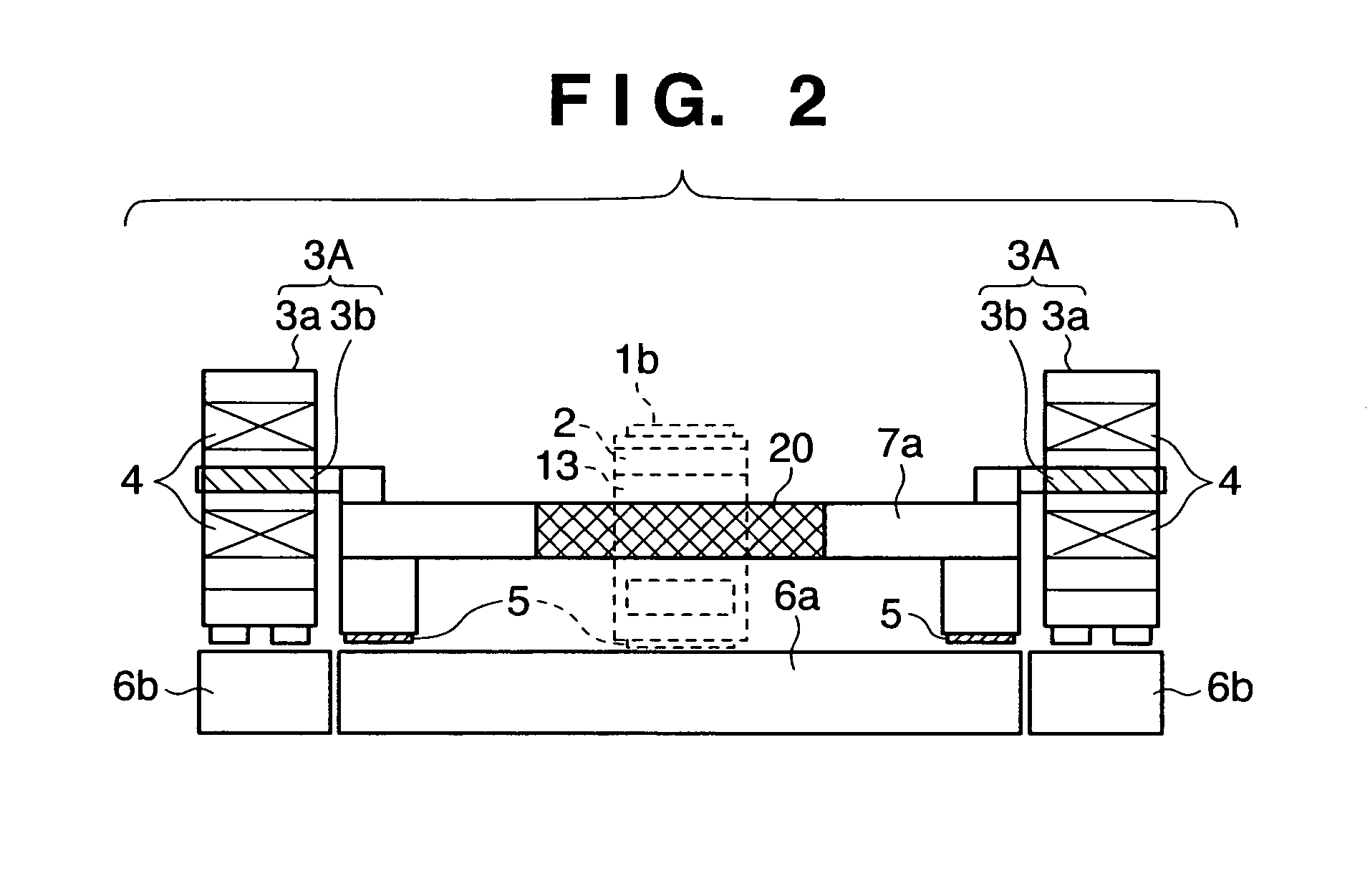
[0070]FIG. 3 is a view showing an alignment apparatus according to the second embodiment of the present invention in a manner corresponding to FIG. 2. FIG. 3 shows an application to a mask stage, which is mounted on a semiconductor exposure apparatus (to be described later), and aligns a mask.

[0071]A mask stage shown in FIG. 3 is an alignment apparatus for a mask 1a arranged in a vacuum atmosphere. A beam 7a (or 7b) and a slider 13 are rigidly connected and can move in only one axial direction, i.e., the X-axis direction (or Y-axis direction). For this reason, the slider 13 itself serves as a temperature-controlled portion 20. A six-axial fine adjustment stage 2, as described in the first embodiment, is arranged on the slider 13.

[0072]Stators 3a, having exciting coils 4 and movable elements 3b having magnets, are provided to move the beams and slider. The stators 3a are supported through hydrostatic bearings 5 on stator bases 6b, which are isolated from a stage base 6a, which suppor...


PUM

PropertyMeasurementUnit
wavelengthaaaaaaaaaa
temperatureaaaaaaaaaa

Abstract

An alignment apparatus includes a first support member having a reference surface which movably supports an object, and a driving unit which moves the object in at least one direction on the reference surface and aligns the object at a predetermined position. The driving unit includes (i) a first driving unit which moves the object in a first direction, and (ii) a second driving unit which moves the object in a second direction, substantially perpendicular to the first direction. The alignment apparatus further includes a second support member which is provided separately from the first support member and supports a heating unit of the driving unit, through a bearing. The first support member supports the object so as to allow the object to move in the first and second directions, and the second support member supports the first and second driving units. The first driving unit has a first movable element which moves the object in the first direction and a first stator which applies a driving force to the first movable element. The second driving unit has a second movable element which moves the object in the second direction and a second stator which applies a driving force to the second movable element. The bearing has a hydrostatic bearing, and the first and second stators are supported on the second support member through the hydrostatic bearing.

Description

FIELD OF THE INVENTION[0001]The present invention relates to a technique for high-speed movement and precise alignment of a stage in a vacuum atmosphere or high-precision scan movement in a semiconductor exposure apparatus, an electron beam drawing apparatus, a precision instrument, or the like, for use in semiconductor device manufacture.BACKGROUND OF THE INVENTION[0002]Along with a recent increase in packing density and speed of semiconductor integrated circuits, the pattern line width of the integrated circuits is decreasing, and higher performance has been demanded for semiconductor manufacturing methods. Accordingly, as printing apparatuses (exposure apparatuses), ones using a KrF laser (248 nm), an ArF laser (193 nm), and an F2 laser (157 nm), are under development. In recent years, there are being developed exposure apparatuses using EUV (Extreme Ultra Violet) light, which is an exposure light having a wavelength far shorter (5 to 15 nm) than a conventional one. Electron beam...

Claims


Application Information

Patent Timeline
Patent Type & Authority Patents(United States)
IPC IPC(8): G03B27/42G03F7/20H01L21/68H01L21/027
CPCF16C29/025F16C32/0603F16C33/748G03F7/70875G03F7/70758G03F7/70816F16C2300/62
Inventor EMOTO, KEIJI
Owner CANON KK
Why Eureka
Try Eureka