Supercharge Your Innovation With Domain-Expert AI Agents!

Lifting device with an adjustable carriage

a technology of lifting device and adjustable carriage, which is applied in the direction of monorails, load-engaging elements, locomotives, etc., can solve the problems of bolts subject to bending stress and loss of lifting height, and achieve the effect of reducing susceptibility to errors

Inactive Publication Date: 2017-05-30
KONECRANES GLOBAL
View PDF11 Cites 6 Cited by
  • Summary
  • Abstract
  • Description
  • Claims
  • Application Information

AI Technical Summary

Benefits of technology

The invention is a lifting device that can easily adjust for different running rails and track widths while minimizing tilting moments. It is connected by a linear guide arrangement, and a centering arrangement ensures that the load carried by the lifting unit is suspended centered under the running rail, regardless of the adjusted track width. The direct connection between the lifting unit and the carriage is eliminated, and the centering arrangement does not require additional vertical construction space. The adjustment device can be a threaded spindle, and the centering device can be a link mechanism with levers located on a horizontal plane.

Problems solved by technology

However, this requires a relatively high space for construction that results in lifting height losses in the case of hoists and is undesirable.
However, the bolt is subject to bending stress.

Method used


Image

  • Lifting device with an adjustable carriage
  • Lifting device with an adjustable carriage
  • Lifting device with an adjustable carriage

Examples


Embodiment Construction

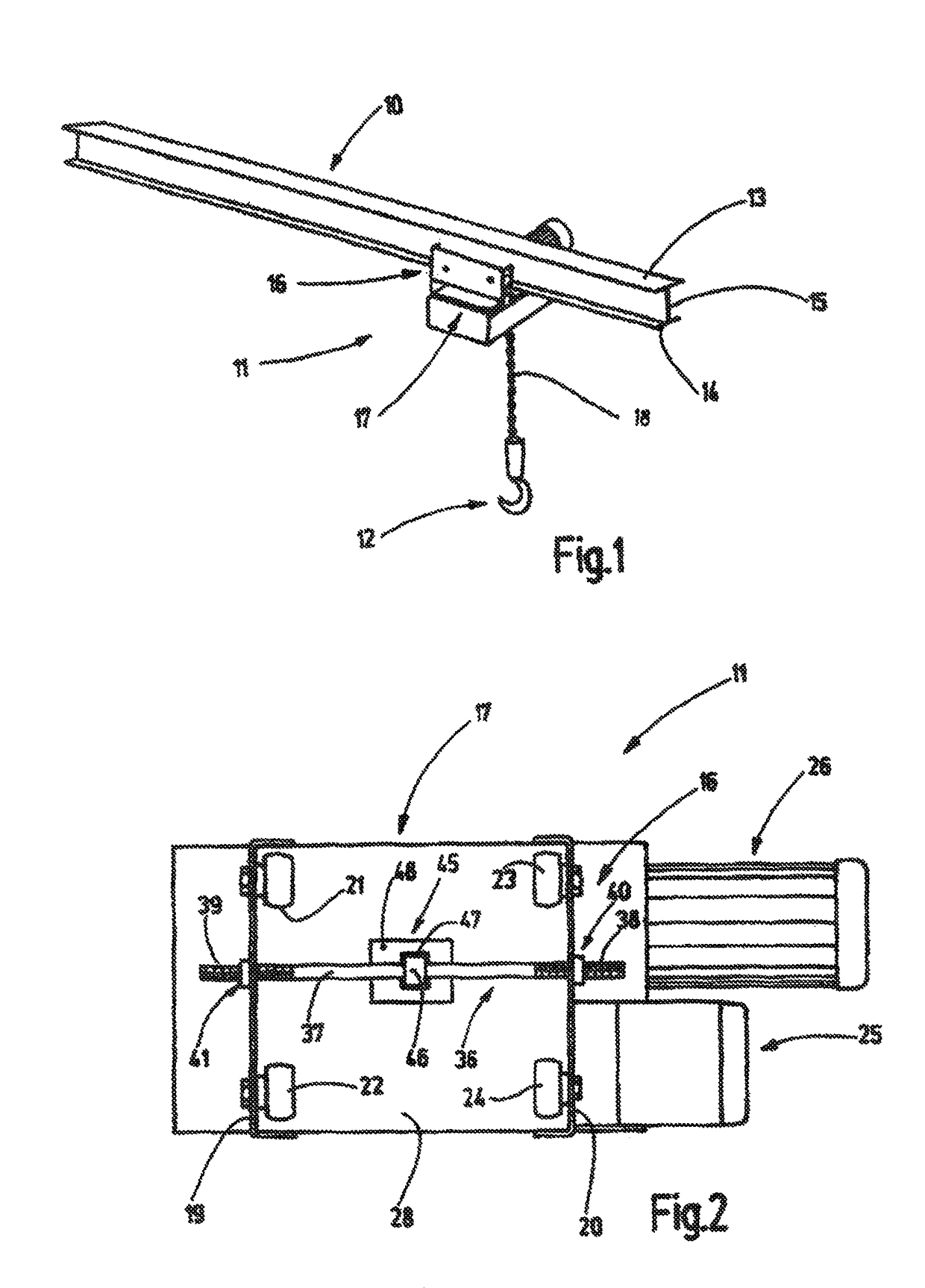
[0037]FIG. 1 shows a crane rail 10 comprising a lifting device 11 that can be moved thereon. The lifting device 11 is disposed for lifting and moving not specifically shown loads. FIG. 1 shows a hook 12 provided therefor.

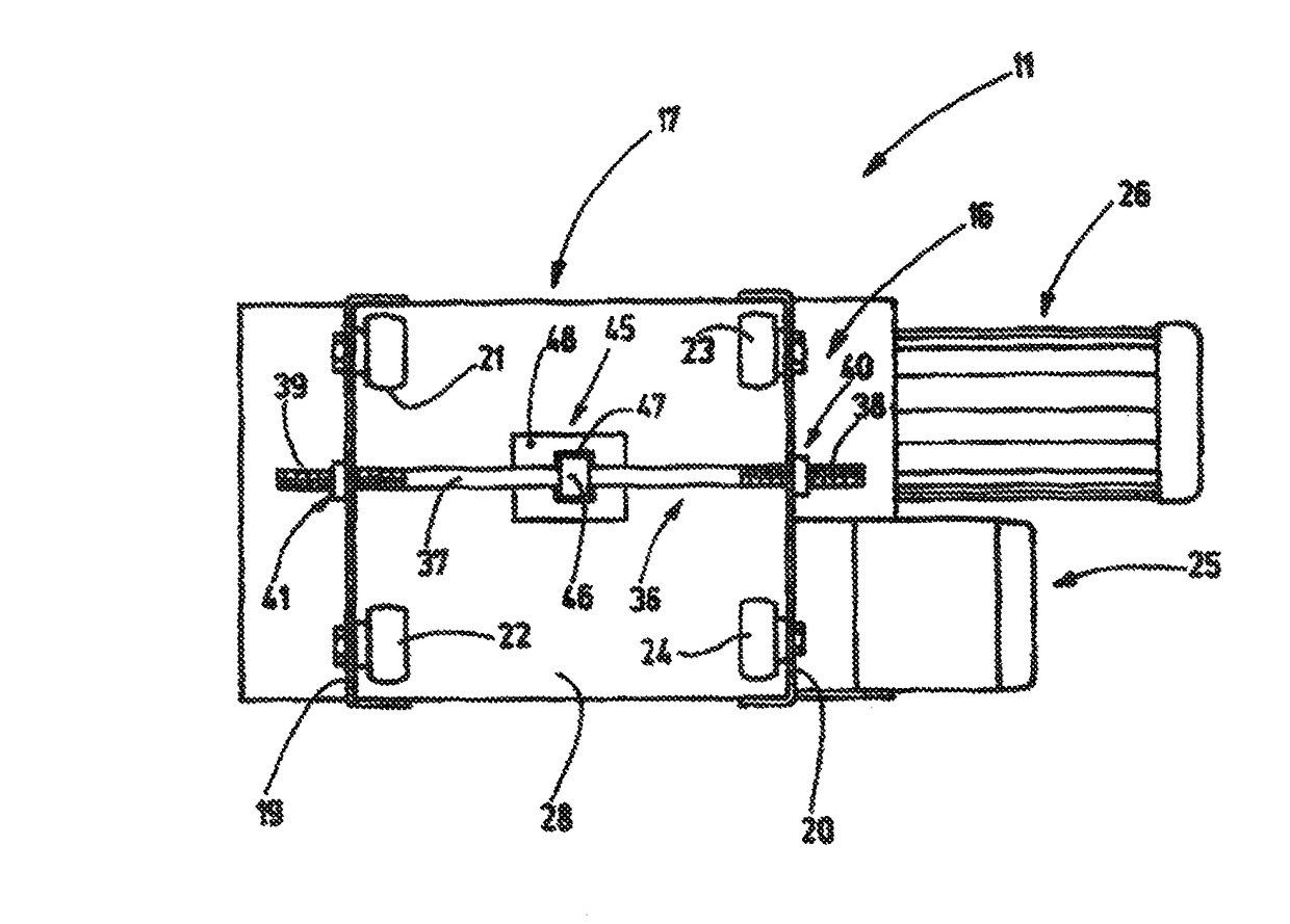
[0038]A cane rail 10 comprises an upper and a lower flange 13, 14 that are connected to each other by means of a vertical bar 15. The latter defines a vertical longitudinal center plane. The crane rail 10 has a given width that is defined by the width of the lower flange 14. The lifting device 11 can be adapted to crane rails having flanges 14 of different widths. For this purpose, the lifting device comprises a correspondingly adjustable carriage 16 that carries the lifting unit 17. The lifting unit 17 carries the hook 12 by means of a chain 18 or another pulling means such as, for example, a rope, a belt or the like.

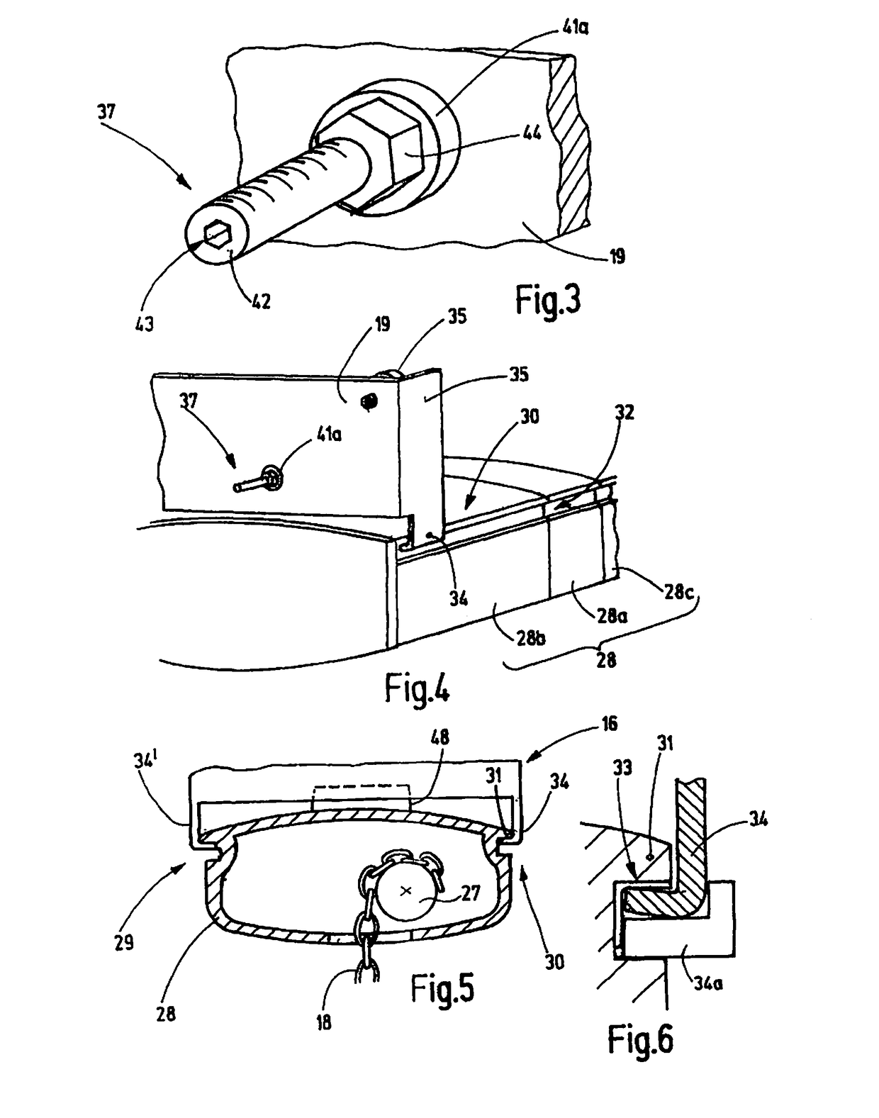
[0039]FIG. 2 shows a schematic plan view of the lifting device 11. The carriage 16 comprises two lateral parts 19, 20 that are preferably arranged par...


PUM


Abstract

The lifting device according to the invention comprises a carriage (16) and a lifting unit (17), which are connected to each other by means of linear guides (29, 30). The carriage (16) comprises two side parts (19, 20) that can be adjusted in view of their distance relative to each other by means of a distance adjustment device (36). In doing so, they are centered by means of a centering device (45) with respect to the lifting unit (17), in particular with respect to the pulling means originating from the lifting unit (17).

Description

CROSS REFERENCE TO RELATED APPLICATION[0001]The present patent application is based upon and claims the benefit of PCT / EP2011 / 073229, filed Dec. 19, 2011; which is based on German patent application nos. 10 2010 061 462.9; filed Dec. 22, 2010, and 20 2010 013 182.0; filed Dec. 22, 2010.TECHNICAL FIELD OF THE INVENTION[0002]The invention relates to a lifting device comprising a carriage, in particular a one-rail underflange carriage.BACKGROUND OF THE INVENTION[0003]Carriages for hoists are also referred to as crane trolleys or as trolley traveling winches. Different embodiments of these have been known. Underflange carriages frequently have two lateral shields which, respectively, support two running wheels, wherein the lateral shields are connected to each other by bolts. It is also possible to mount the load, e.g., in the form of a chain block hoist, to the bolt. Such a carriage is known, for example, from publication DE 10 2004 009 062 A1.[0004]The corresponding running rails exis...

Claims


Application Information

Patent Timeline
Patent Type & Authority Patents(United States)
IPC IPC(8): B66C11/06B66C9/02
CPCB66C11/06B66C9/02B61B13/04B61C13/04
Inventor BUHLMAYER, REINERWEINGARTNER, JURGEN
Owner KONECRANES GLOBAL
Features
  • R&D
  • Intellectual Property
  • Life Sciences
  • Materials
  • Tech Scout
  • Unparalleled Data Quality
  • Higher Quality Content
  • 60% Fewer Hallucinations
Learn More