

Method for reprocessing spent nuclear fuel and centrifugal extractor therefor
a centrifugal extractor and nuclear fuel technology, applied in the field of reprocessing spent nuclear fuel, can solve the problems and achieve the effect of difficult to isolate and recover reprocessed plutonium and high proliferation suppressing effects
- Summary
- Abstract
- Description
- Claims
- Application Information
AI Technical Summary
Benefits of technology
Problems solved by technology
Method used
Image

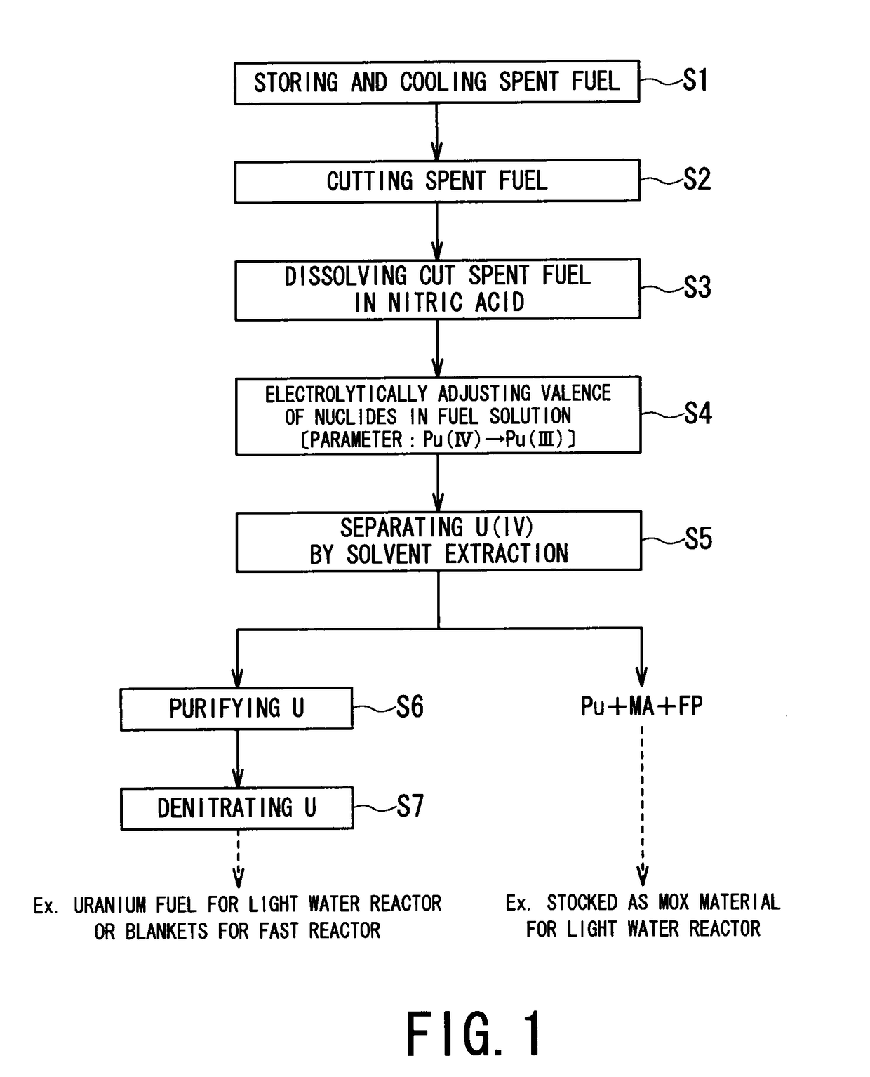
Examples
first embodiment
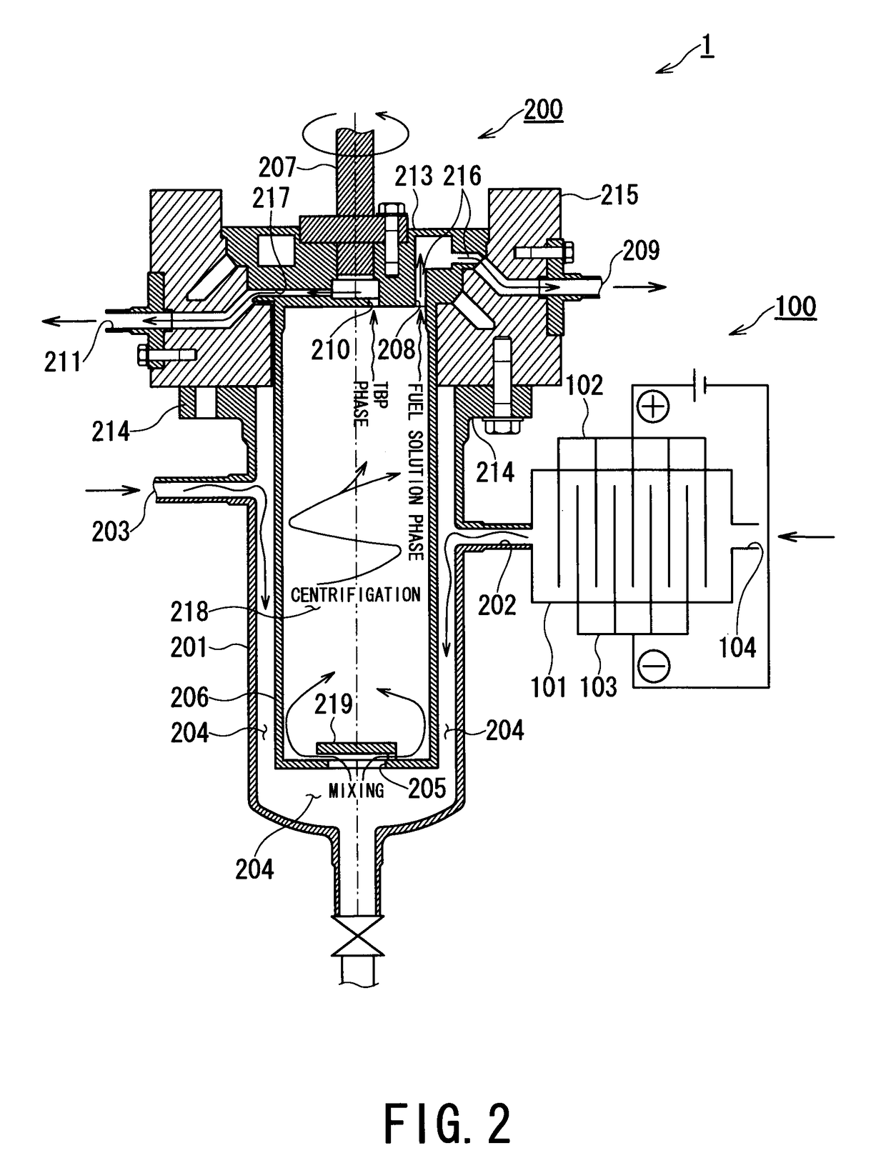
[0060]FIG. 2 is a vertical cross-sectional view showing the centrifugal extractor according to the present invention.
[0061]As shown in FIG. 2, a centrifugal extractor 1 of this embodiment includes an electrolytic reduction unit 100 and a centrifugal extraction unit 200.
[0062]The electrolytic reduction unit 100 of the centrifugal extractor 1 is connected to the centrifugal extraction unit 200. The electrolytic reduction unit 100 includes an electrolytic reduction vessel 101, electrodes (anode 102 and cathode 103), and a fuel solution inlet 104.
[0063]The fuel solution inlet 104 of the electrolytic reduction unit 100 is connected to a transfer canal through which the fuel solution obtained in the step S3, i.e., a fuel solution containing FP and MA, is transferred.
[0064]The electrolytic reduction vessel 101 of the electrolytic reduction unit 100 contains electrodes (anode 102 and cathode 103). In the electrolytic reduction vessel 101, the dissolved nuclides contained in the fuel solutio...
second embodiment
[0085]FIG. 3 is a vertical cross-sectional view showing the centrifugal extractor according to the present invention.
[0086]The second embodiment is an example in which the structure of the electrolytic reduction unit 100 of the centrifugal extractor 1 of the first embodiment may be modified. The structures identical to those of the first embodiment shown in FIG. 2 are represented by the same reference characters and the descriptions therefor are omitted. The structures modified from the first embodiment and newly added structures are represented by corresponding reference characters followed by letter “A” and described.
[0087]A centrifugal extractor 1A of this second embodiment includes an electrolytic reduction unit 100A, as shown in FIG. 3. The electrolytic reduction unit 100A includes a partition 105A, an anode chamber 106A housing an anode 102 and a cathode chamber 107A housing a cathode 103, both chambers 106A and 107A being separated by the partition 105A. Further, it is to be ...
third embodiment
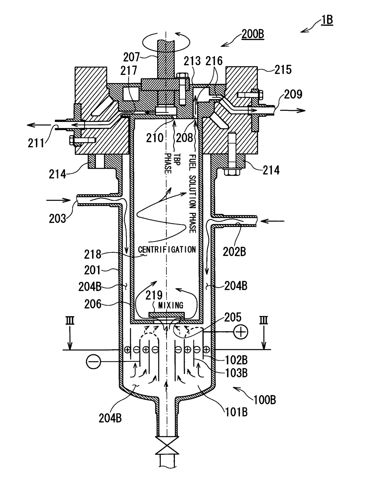
[0091]FIGS. 4A and 4B show the centrifugal extractor according to the present invention. FIG. 4A is a vertical cross-sectional view of a centrifugal extractor and FIG. 4B is a cross-sectional view taken along line III-III in FIG. 4A.
[0092]The third embodiment is another example in which the structure of the electrolytic reduction unit 100 of the centrifugal extractor 1 of the first embodiment may be modified. The structures identical to those of the first embodiment are represented by the same reference characters and the descriptions therefor are omitted. The structures modified from the first embodiment and newly added structures are represented by corresponding reference characters followed by letter “B” and described.
[0093]A centrifugal extractor 1B of this third embodiment includes an electrolytic reduction unit 100B that includes an anode 102B, a cathode 103B, a fuel solution feed port 202B, and a mixing space 204B (electrolytic reduction vessel 101B), as shown in FIG. 4A. In ...
PUM
| Property | Measurement | Unit |
|---|---|---|
| flow rate | aaaaa | aaaaa |
| flow rate | aaaaa | aaaaa |
| feed flow rate | aaaaa | aaaaa |
Abstract
Description
Claims
Application Information