
Magnetically coupled flywheel

a magnetic coupling and flywheel technology, applied in the field of flywheels, can solve the problems of loss of stored energy, insensitive flywheel systems to environmental factors, and fluctuation of electrical power from the grid, so as to reduce imbalance forces

Active Publication Date: 2017-05-30
ZOOZ POWER LTD
View PDF21 Cites 8 Cited by
  • Summary
  • Abstract
  • Description
  • Claims
  • Application Information

AI Technical Summary

Benefits of technology

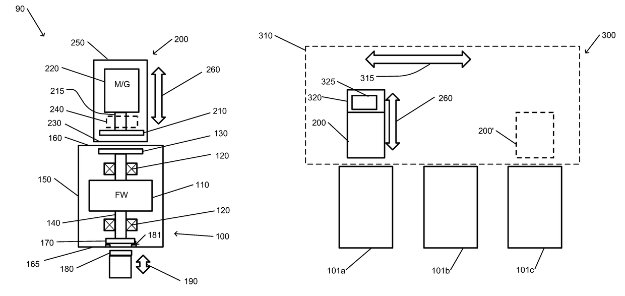
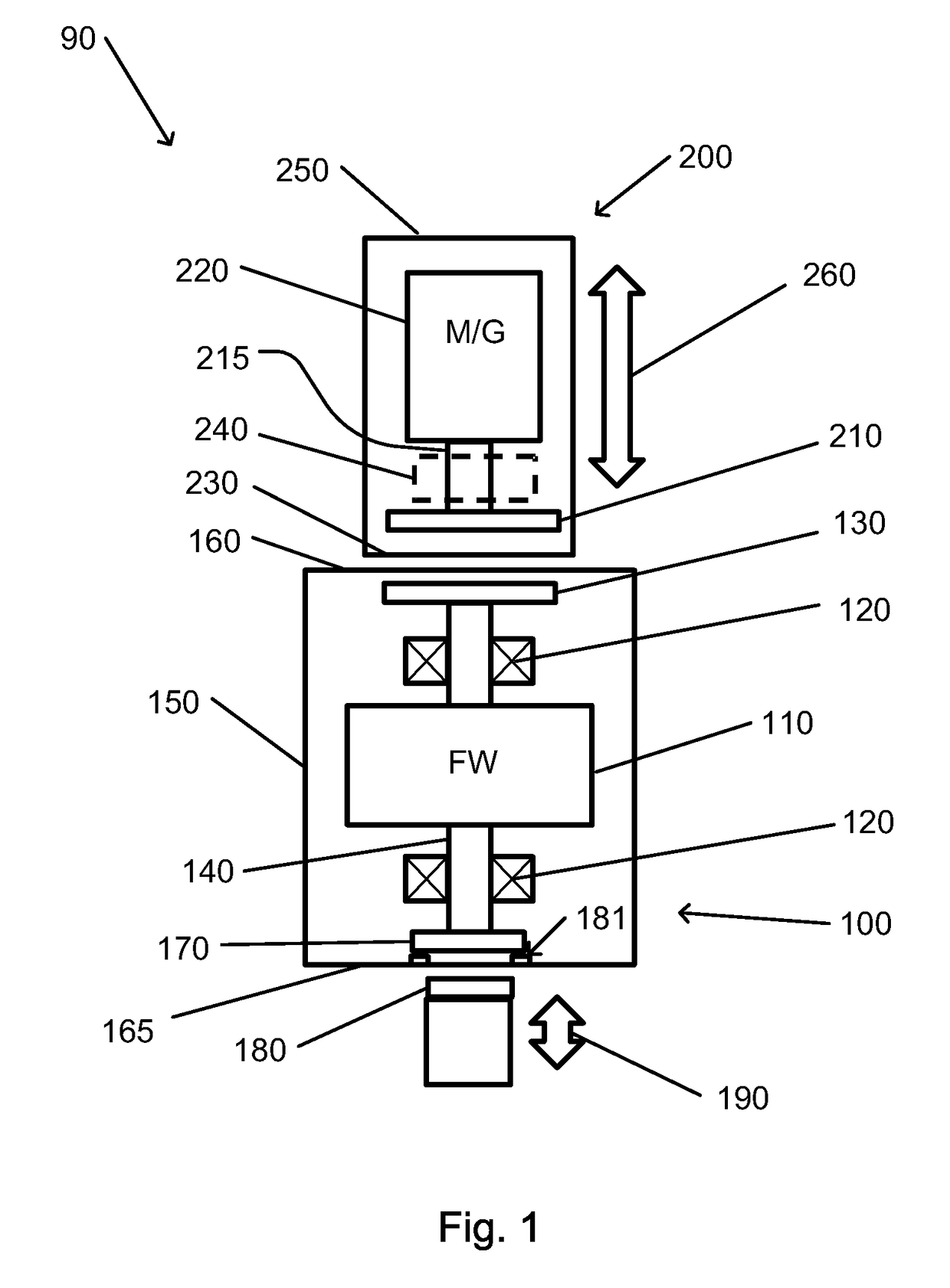
[0012]There is thus provided, in accordance with an embodiment of the present invention, a stabilization system for a rotating load, the system including: a mechanical bearing to continuously support a shaft of the rotating load so as to hold the shaft at a substantially fixed axis of rotation; a magnetic stabilization assembly including a plurality of electromagnets arranged around the shaft; a control circuitry for controlling a resultant magnetic field generated by the electromagnets such that the magnetic field acts on a ferromagnetic element of the shaft to reduce imbalance forces acting on the shaft.

Problems solved by technology

During the store phase, various frictional forces may act to slow the speed of rotation of the flywheel and to cause loss of the stored energy.
For example, the cost of electrical power from the grid may vary periodically.
Flywheel systems may also be relatively insensitive to environmental factors such as temperature changes.

Method used


Image

  • Magnetically coupled flywheel
  • Magnetically coupled flywheel
  • Magnetically coupled flywheel

Examples


Embodiment Construction

[0058]In the following detailed description, numerous specific details are set forth in order to provide a thorough understanding of the invention. However, it will be understood by those of ordinary skill in the art that the invention may be practiced without these specific details. In other instances, well-known methods, procedures, components, modules, units and / or circuits have not been described in detail so as not to obscure the invention.

[0059]Embodiments of the invention may include an article such as a computer or processor readable medium, or a computer or processor storage medium, such as for example a memory, a disk drive, or a USB flash memory, encoding, including or storing instructions, e.g., computer-executable instructions, which when executed by a processor or controller, carry out methods disclosed herein.

[0060]In accordance with embodiments of the present invention, a flywheel energy storage system includes a flywheel. The flywheel, as well as any shaft, axle, or...


PUM


Abstract

A stabilization system for a rotating load, such as a flywheel, includes a mechanical bearing to continuously support a shaft of the rotating load so as to hold the shaft at a substantially fixed axis of rotation. A magnetic stabilization assembly includes a plurality of electromagnets arranged around the shaft. Control circuitry for controls a resultant magnetic field generated by the electromagnets such that the magnetic field acts on a ferromagnetic element of the shaft to reduce imbalance forces acting on the shaft.

Description

CROSS-REFERENCE TO RELATED APPLICATIONS[0001]This application is a National Phase Application of PCT International Application No. PCT / IL2013 / 050630, International Filing Date Jul. 24, 2013, claiming the benefit of U.S. Provisional Patent Application No. 61 / 677,056, filed Jul. 30, 2012, of U.S. Provisional Patent Application No. 61 / 722,174, filed Nov. 4, 2012, and of U.S. Provisional Patent Application No. 61 / 773,158, filed Mar. 6, 2013, each of which is hereby incorporated by reference.FIELD OF THE INVENTION[0002]The present invention relates to flywheels. More particularly, the present invention relates to a magnetically coupled flywheel.BACKGROUND OF THE INVENTION[0003]Electrical energy storage systems are of use both to producers and consumers of electrical energy. Storage systems for electrical energy may include storage batteries or other chemistry-based storage systems, capacitors or other electrically-based storage systems, thermal storage, or mechanical energy storage syste...

Claims


Application Information

Patent Timeline
Patent Type & Authority Patents(United States)
IPC IPC(8): H02K7/02F16F15/315H02K7/09F16C32/04F16F15/30F16F15/03H02K7/08
CPCH02K7/025F16C32/0402F16C32/0446F16C32/0451F16F15/03F16F15/30F16F15/3156H02K7/02H02K7/09H02K7/083Y02E60/16F16C2361/55F16C19/527F16F15/005F16F15/18H02K7/085
Inventor BEN DAVID, ILANZOHAR, NIRPINCU, DAVID
Owner ZOOZ POWER LTD
Learn More