
Connecting structure for exteriorly connecting a battery cell and a load circuit by using two connecting graphite blocks

a technology of connecting structure and load circuit, which is applied in the direction of cell components, cell component details, coupling device connections, etc., can solve the problems of battery cell failure, contact portion heat up and consume power of battery cell, and relatively high cost of welding procedure, etc., to achieve high conductivity connection, less cost, and high conductive connection

Active Publication Date: 2017-06-06
ENERGY CONTRROL LTD
View PDF5 Cites 0 Cited by
  • Summary
  • Abstract
  • Description
  • Claims
  • Application Information

AI Technical Summary

Benefits of technology

The present invention provides a high conductivity connecting structure for exteriorly connecting a battery cell and a load circuit using two connecting graphite blocks. This direct contact connection eliminates the need for welding and reduces production costs. The connecting graphite blocks are connected to the electrode terminals of the battery cell in a close contact manner to connect them to the load circuit. The bias between the positive and negative electrode terminals allows the carbon particles of the connecting graphite blocks to substitute for the foreign matters on the battery cell terminals and fill the voids, resulting in a smooth current discharge due to reduction of external connection resistance.

Problems solved by technology

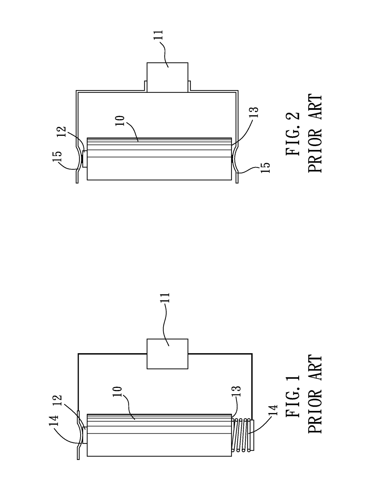
Due to direct contact between the electrode terminals and the metal terminals, a high contact resistance will be caused at the respective contact portions of the electrode terminals and the metal terminals, so that when the battery cell is switched on, the contact portion will heat up and consume power of the battery cell.
It is to be noted that, intense heat caused during the spot welding will be transmitted to the battery cell to cause damages to interior of the battery cell, such as: breakage of the seal gasket, and rupture of the isolating layers, and etc, thus leading to failure of the battery.
In addition, the cost of the welding procedure is relatively high.
U.S. Pat. No. 4,382,116 fails to disclose an external connecting structure for exteriorly connecting the battery to a load circuit by using two graphite blocks.
Hence, it can be found that the conventional connection between a battery cell and a load circuit cannot satisfy the basic requirements of the cost economics, high conductivity and high relativity.

Method used


Image

  • Connecting structure for exteriorly connecting a battery cell and a load circuit by using two connecting graphite blocks
  • Connecting structure for exteriorly connecting a battery cell and a load circuit by using two connecting graphite blocks
  • Connecting structure for exteriorly connecting a battery cell and a load circuit by using two connecting graphite blocks

Examples


Embodiment Construction

[0025]The present invention will be easily comprehended from the following description when viewed together with the accompanying drawings, which show, for purpose of illustrations only, the preferred embodiment in accordance with the present invention.

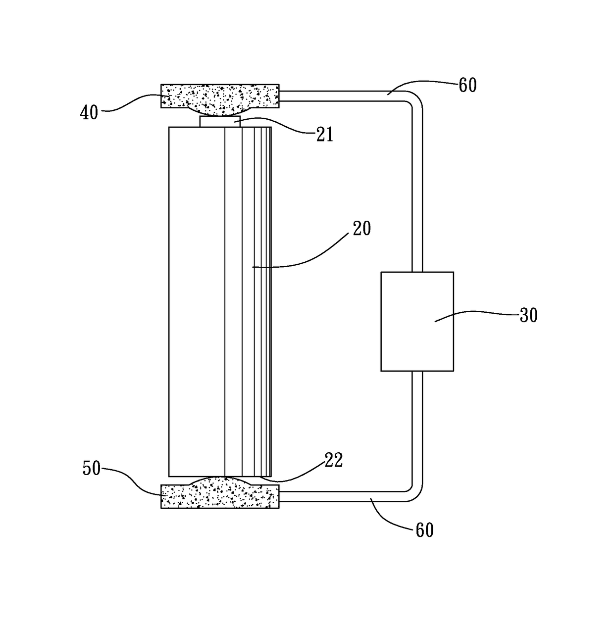
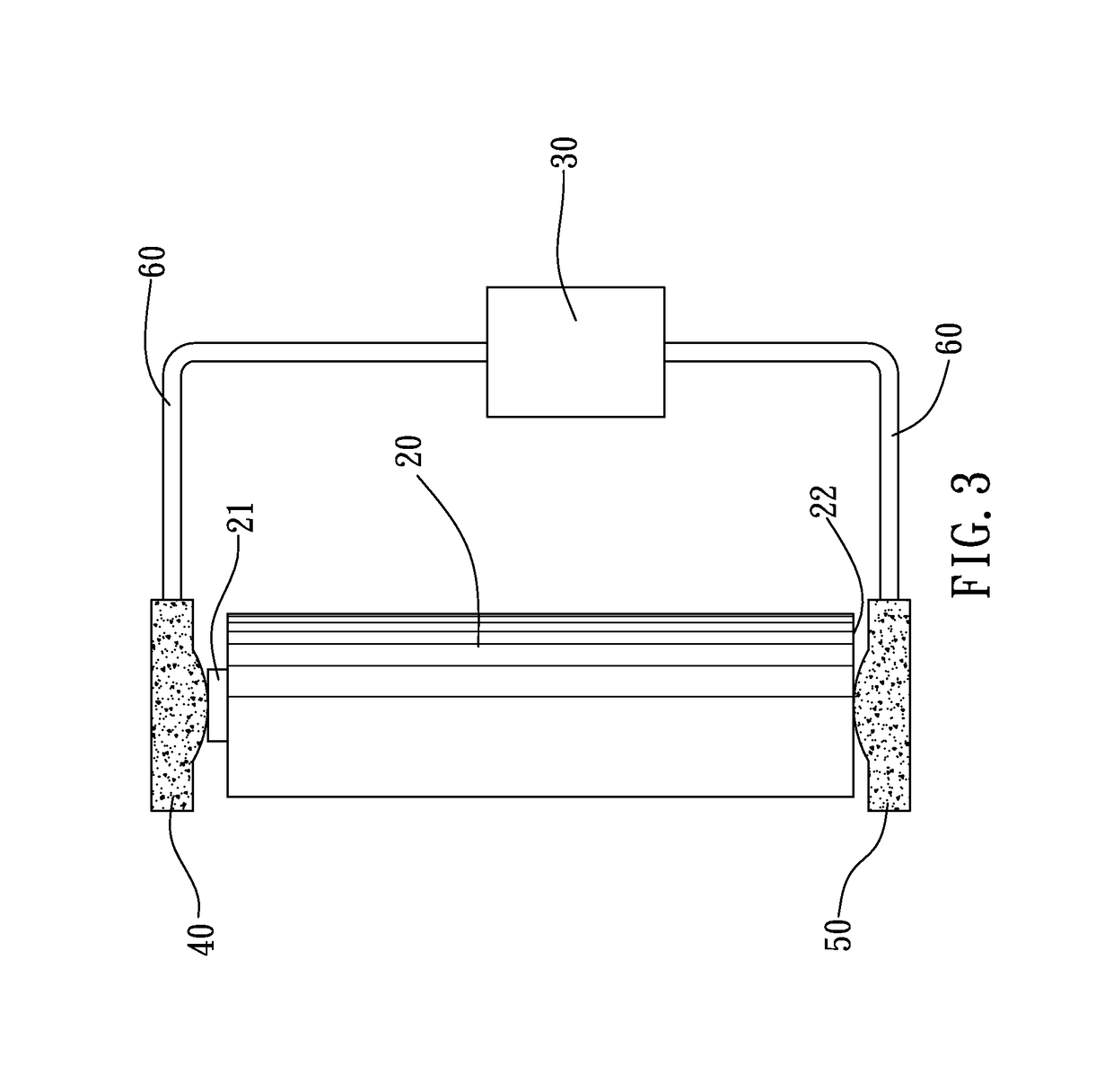
[0026]Referring to FIG. 3, a connecting structure for exteriorly connecting a battery cell 20 and a load circuit 30 in accordance with the present invention comprises a first connecting graphite block 40 and a second connecting graphite block 50 which are electrically connected to a positive electrode terminal 21 and a negative electrode terminal 22 of the battery cell 20, and then connected to the load circuit 30. This connecting structure provides a relatively high electric conductivity between the battery cell 20 and the load circuit 30.

[0027]The battery cell 20 is a cylindrical battery cell and exteriorly provided on both ends thereof with the positive electrode terminal 21 and the negative electrode terminal 22 which are made of ...


PUM

PropertyMeasurementUnit
conductivityaaaaaaaaaa
contact resistanceaaaaaaaaaa
connection conductivityaaaaaaaaaa

Abstract

A connecting structure for exteriorly connecting a battery cell and a load circuit by using two graphite connecting graphite blocks, wherein the positive and negative electrode terminals of the battery cell are made of nickel, the battery cell is connected to the load circuit by the two connecting graphite blocks, respectively. The graphite is inexpensive and resistant to oxidation; whereas, the connecting graphite blocks and the nickel-plated metal made electrode terminals of the battery cell will dissolve in each other to form a carbon-nickel alloy after being brought into contact with one another, thus ensuring a smooth large-current discharge because of the reduction in resistance of external connection.

Description

[0001]This application is a continuation in part of U.S. patent application Ser. No. 12 / 834,834, which claims the benefit of the earlier filing date of Jul. 12, 2010. Claims 1-4 of this application are revised from claims 1 and 4-6 of the U.S. patent application Ser. No. 12 / 834,834, respectively.BACKGROUND OF THE INVENTION[0002]Field of the Invention[0003]The present invention relates to a non-welding and oxidation resistant connecting structure for exteriorly connecting a battery cell and a load circuit at a high conductivity.[0004]Description of the Prior Art[0005]Referring to FIG. 1 showing a conventional connecting structure for exteriorly connecting a single battery cell and a load circuit, wherein the single battery cell 10 and the load circuit 11 are connected in such a manner that a positive electrode terminal 12 and a negative electrode terminal 13 of the battery cell 10 each are brought into direct contact with a metal terminal 14 first, and then the metal terminals 14 wil...

Claims


Application Information

Patent Timeline
Patent Type & Authority Patents(United States)
IPC IPC(8): H01M2/26H01M2/28H01R13/03H01R13/02H01M2/30H01M50/534H01M50/541H01M50/562
CPCH01M2/26H01R13/03H01M2/30H01R13/025Y02E60/10H01M50/562H01M50/534
Inventor WU, DONALD P. H.
Owner ENERGY CONTRROL LTD
Learn More