Devices in the third category are not
germane to the current discussion because they themselves do not provide the chair-lifting function.
Unfortunately, some infirm and
older people who replace a favorite, comfortable, ordinary chair, such as a recliner, with one of the rising-and-tilting models are disappointed because of reduced comfort.
Consequently, if the user's
buttocks remain toward the rear of the seat, far behind the heels, standing is more difficult, because the body's
center of mass is too far back, requiring a greater forward-leaning angle of the
torso.
Consequently, prior-art retrofits that fail to raise the front portion of the seat at least this much are deficient.
A chair that is too high leads to increased pressure at the popliteal fold (underside of knees), decreasing
blood circulation and increasing pressure on the nerve.
It is concluded that variation beyond the 50-mm (2-inch) range sited by these sources is unacceptable.
Thus, a chair-lifting retrofit must be limited to at most
A retrofit lacking this attribute lacks general usefulness, because for many chairs, including most popular recliner models, no such space is available—the mechanism of the chair itself already occupies virtually all the space between its base and its seat.
(a) It fails to have the first desirable attribute; that is, ΔR is too small. Thus the prior-art retrofit fails to provide sufficient sit-to-stand assistance, the very task it purports to accomplish.
(b) It fails to have the second desirable attribute; that is, RSIT is too large. Thus the prior-art retrofit makes sitting uncomfortable.
(c) It fails to have the third desirable attribute; that is, it requires custom
adaptation to be effectively and safely used with different types of chairs. For example, some prior-art retrofits, as will be shown, cause the chair to tilt forward. To avoid danger in such cases, the chair must be well secured to the retrofit. Yet each chair is different, so a custom scheme must be developed to secure it to the retrofit. Consequently, prior-art retrofits that tilt forward lack general usefulness, because they cannot be adapted to a wide variety of chairs without costly and time-consuming custom
engineering. Moreover, in most cases, the chair must be modified to achieve safe retrofit-to-chair attachment; for example, the chair's frame members must be penetrated by fasteners such as screws, which is undesirable.
(d) It fails to have the fourth desirable attribute; that is, its mechanism fails to avoid occupying some of the space between the base of the chair and the underside of the seat. Such a retrofit lacks general usefulness, because for many chairs, including most popular recliner models, no such space is available—the mechanism of the chair itself already occupies virtually all the space between floor and seat. Typically, prior-art retrofits suffer from shortcoming (d) because they attempt thereby to avoid shortcoming (b).
(e) It fails to have the fifth desirable attribute; that is, it cannot be easily transported, deployed and un-deployed, for one or more reasons. It may require modification of the chair, or otherwise involve difficult and time-consuming
assembly. It may be monolithic and therefore be too cumbersome and heavy to move easily. Conversely, it may disassemble into too many pieces, and therefore be difficult to manage.
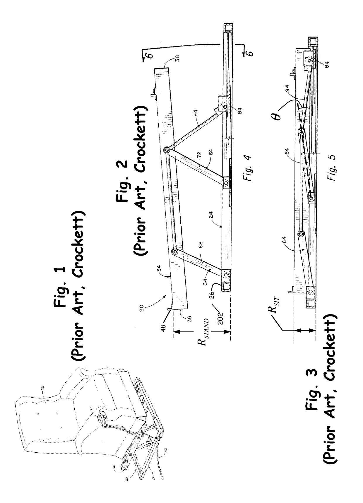
Crockett's chair-lifting retrofit suffers from shortcoming (b): RSIT is too large.
Consequently, Crockett's retrofit fails to provide comfortable sitting for the user.
Crockett's retrofit further suffers from shortcoming (a); that is, ΔR is too small.
Consequently, Crockett's retrofit provides insufficient sit-to-stand assistance for many users.
The general usefulness of Crockett's retrofit is thereby compromised.
Finally, Crockett's retrofit suffers from shortcoming (e), not only because it may require modification of the chair, as already mentioned, but also because it is a monolithic structure which is likely to be too heavy and cumbersome to be easily transported and stored.
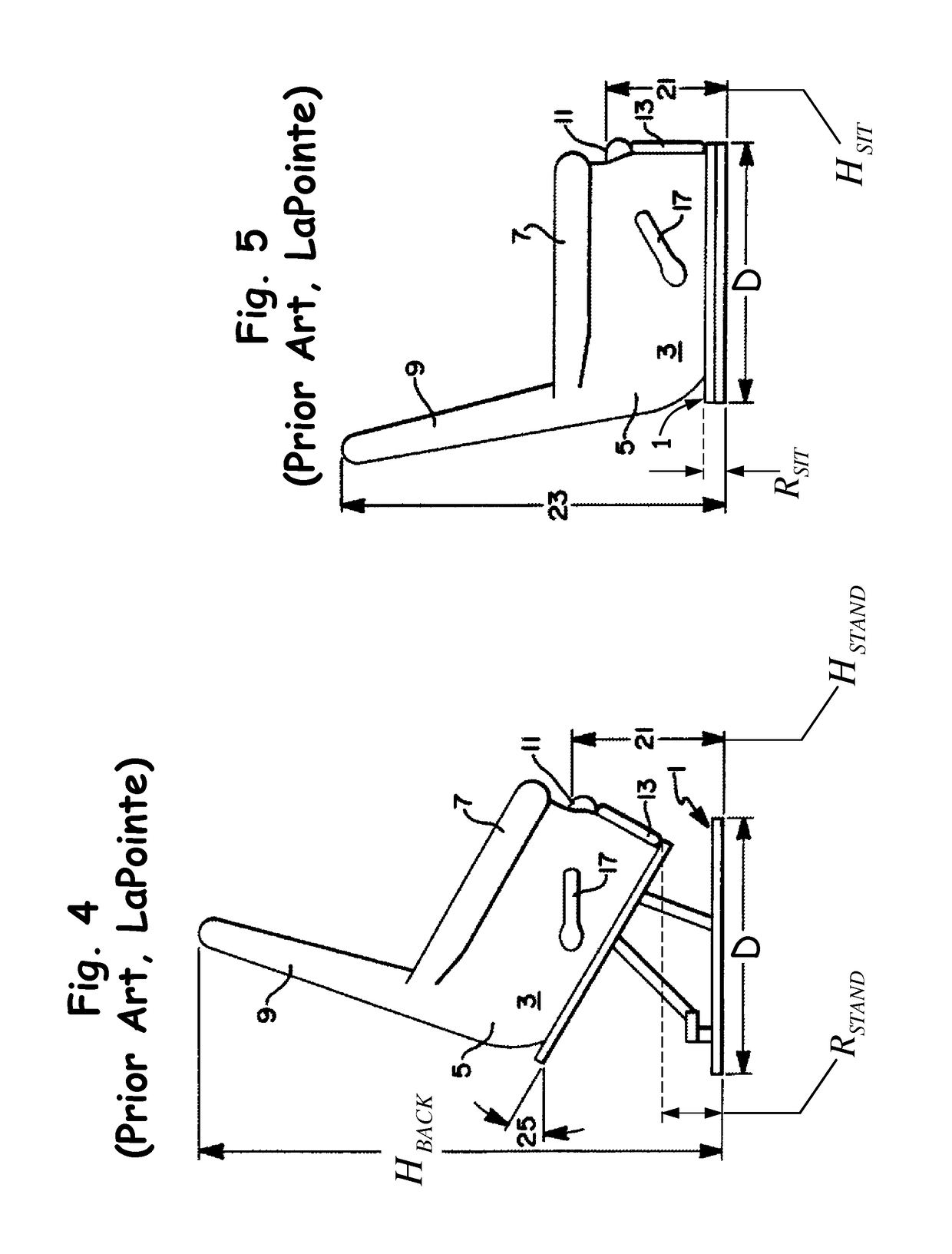
To be sure, because of the forward tilt angle that LaPointe provides (29°), the rear of the seat is raised much more, but this is largely ineffective in helping the user to stand, because, as previously explained following equation (12), to be in contact with the rear portion of the seat, the user's center of gravity must be so far back that it cannot possibly be forward of the heels, which is required to achieve the sit-to-stand task.
Thus, LaPointe's retrofit provides far too little seat rise to help appreciably with the sit-to-stand process.
Although this assumption was apparently valid for the particular type of chair he was considering, as described (per LaPointe) in U.S. Pat. No. 4,367,895, it is not valid for most chairs, particularly popular modern recliners, whose internal mechanisms already fill this space.
Consequently, LaPointe's retrofit can only be used with a very limited subset of chairs.
Finally, LaPointe's retrofit suffers from shortcoming (e), not only because it requires modification of the chair, as already mentioned, but also because it is a monolithic structure which is likely to be too heavy and cumbersome to be easily transported and stored.
Consequently, Rudes's retrofit provides insufficient sit-to-stand assistance for certain users.
Although Rudes describes his seat-height overhead of 4.5 inches as “unusually compact”, this overhead is actually very large, being seriously in violation of requirement (19).
Consequently, Rudes retrofit will produce great discomfort while the user is sitting.
Rudes's retrofit further suffers from shortcoming (c), in that it causes the chair to tilt forward, and, as previously mentioned, a retrofit providing forward tilting requires, for safety reasons, means to secure the chair to the retrofit.
This makes it highly unlikely that such a retrofit can be universally adapted to a wide variety of chairs.
Indeed, although Rudes contends, in column 1, lines 45-46, that his retrofit is “universally adaptable to most previously manufactured chairs”, the scheme he actually describes is hardly universally adaptable.
This is not adaptable, for example, to chairs with four legs rather than a base frame.
Nor is it adaptable to rocker-style recliners with round bases.
Thus, much custom
engineering and expense is required to adapt Rudes retrofit to a wide variety of chairs, thereby compromising its general usefulness.
Moreover, even if a chair happens to accommodate Rudes attachment scheme, alteration of the chair itself is still required, in the form of the “threaded connectors” that must be driven into the wooden frame of the chair.
This is undesirable; it is preferable not to alter the chair at all.
Finally, Rudes's retrofit suffers from shortcoming (e), not only because it requires modification of the chair, as just mentioned, but also because it is a monolithic structure that is likely to be too heavy and cumbersome to be easily transported and stored.
That is, devices designed for other applications, despite being often entitled “low profile”, are typically far too cumbersome to permit comfortable sitting; that is, the minimum height from floor to platform, defined by equation (6) as RSIT, is too large to satisfy equation (19), which states that RSIT should be less than 50 mm (the smaller the better) for comfortable sitting.
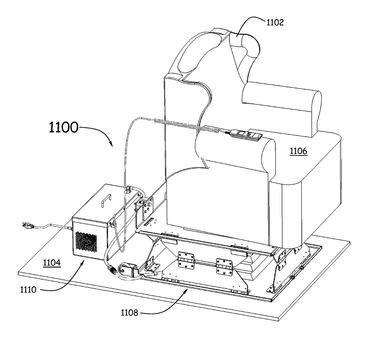
(a) In the high position, the important part of the chair seat—the front, as explained in Section 1.2 above—is raised by an amount sufficient to allow even a demanding user to accomplish the sit-to-stand task. For example, in the prototype embodiment, the chair seat is lifted by ΔH≈236 mm. This more than satisfies the requirement expressed by equation (18), namely ΔH≧229 mm. Consequently, unlike all prior-art retrofittable chair lifters known, the lifting apparatus provides adequate seat rise ΔH even for demanding users.
(b) In the low position, where the user of the chair must sit for extended periods, the lifter
assembly produces a seat height that is only modestly higher than normal, by an amount RSIT≈39 mm. This easily meets the requirement expressed by equation (19), namely RSIT≦50 mm. Consequently, unlike all prior-art retrofittable chair lifters known—except for those that side-step the issue by introducing shortcoming (d), thereby ruling out applicability to many existing chairs—the lifting apparatus described herein causes no sitting discomfort because RSIT is small.
(c) The lifting apparatus is universally retrofittable to all types of chairs, because the chair is simply placed on the platform. The top surface of the platform is substantially planar, so it acts as a surrogate floor for the chair. No additional, chair-specific
engineering is necessary. Because the lifting apparatus does not cause the chair to tilt, the chair does not have to be secured to the platform, so again, no chair-specific engineering is required; at most, shifting of the chair on the platform may be eliminated by simple
adhesive pads affixed to the platform. The chair is not altered in any way.
(d) The lifting apparatus does not use any space between the base of the chair and the seat, because the platform on which the chair rests is substantially flat over the entire
footprint of the chair. Nothing projects upward from the platform; consequently, it creates no interference with any structure or mechanism of the chair.
(e) The lifting apparatus is easily deployable, movable and storable, for two reasons.
First, it does not require any attachment to the chair or modification thereof.
Second, it separates into just a few relatively light, compact, manageable pieces that may be easily move and stored.

