Modular, fluid thermal transfer device

a fluid thermal and module technology, applied in the field of modules, fluid thermal transfer devices, can solve the problems of inability to join directly to, pre-formed pavers or slab units, and incompatibility of conventional thermal transfer systems, and achieve the effect of disassembly of the device and high efficiency of thermal energy transfer

Active Publication Date: 2017-06-20
THERMA HEXX
View PDF25 Cites 14 Cited by
  • Summary
  • Abstract
  • Description
  • Claims
  • Application Information

AI Technical Summary

Benefits of technology

[0015]The modularity of the thermal transfer devices allows for a number of benefits. For example, the modularity of the thermal transfer devices allows for the manufacture of devices to match a particular size paver / slab / stone unit. The modularity also allows the thermal transfer devices to be arrayed with other paver / slab / stone units creating a highly efficient transfer of thermal energy between a fluid and a thermal mass. In addition to the foregoing, the modular thermal transfer devices allow for disassembly and re-assembly of an array of modular thermal transfer devices. The ability to disassemble the device can allow for repairs to the system, replacement of damaged or broken paver / slabs, or easy access to the area below a paver surface. Still further, the modularity of the thermal transfer devices can allow devices to be removed and replaced without having to remove an entire array.

Problems solved by technology

Unfortunately, such conventional thermal transfer systems typically include one or more limitations.
For example, conventional thermal transfer systems are typically not compatible with, and thus cannot join directly to, pre-formed paver or slab units, such as paver slab units elevated on pedestals.
Furthermore, conventional thermal transfer systems often require a continuous monolithic mass to contain the tubes and are difficult to repair.
Conventional thermal transfer systems also often do not allow for disassembly, re-assembly, or other rearranging of an initial configuration.
Also, conventional thermal transfer systems typically have manufacturing limits of continuous extruded tubing having an interior surface that is smooth and linear.
Such linear flow can lead to inefficiency in the transfer of thermal energy between the fluid and tube surface due to a boundary layer that is created by the linearly flowing fluid.
Additionally, the long continuous runs of tubing can expand and contract causing ticking and clicking noises within the system.
Also, upon deterioration of the concrete slab that encases the tubing, conventional thermal transfer systems require replacement of the slab as well as the tubing due to damage to the tubing often created during the demolition of the concrete slab.
The constant expansion and contraction of the tubing in conventional thermal transfer systems accelerates the deterioration of the concrete slab causing premature failure of the concrete.
Along related lines, if the tubing is subject to freezing without the proper anti freeze in the fluid, failure of the tubing can result, thus necessitating the demolition / replacement of the concrete slab in order to repair the tubing.
In addition to the foregoing, limitations of current pipe or tube connectors can compound the drawback of conventional thermal transfer systems.
When removed, conventional compression type connectors often leave a mark or deformation on the surface of the tube that they were locked onto.
Such deformations can cause leakage when the tube is reconnected.
As such, conventional compression-type connectors are often unsatisfactory for re-uses and systems that require connection and disconnection of tubes (such as modular or reconfigurable systems).
Conventional glue-on-type connectors often require more time to install and have a potential to leak.
Furthermore, when conventional glue-on-type connectors do leak they typically cannot be replaced.
Conventional glue-on-type connectors also commonly do not allow for disassembly reassembly.
In addition to the foregoing, conventional glue-on-type connectors are typically limited to use with materials that are suitable for gluing.
Nonetheless, conventional push-on-type O-ring connectors also present some limitations.
In addition to the foregoing, conventional thermal transfer systems commonly do not allow for nesting with paver / slabs that are raised on pedestals.
Conventional thermal transfer systems also often do not allow for easy disassembly and reassembly without causing damage to the components.
Still further conventional thermal transfer systems often utilize connecters that leak or are otherwise faulty.
Additionally, conventional thermal transfer systems are not practical or economical to manufacture in modular form.
Accordingly, there are a number of disadvantages with conventional thermal transfer systems that can be addressed.

Method used


Image

  • Modular, fluid thermal transfer device
  • Modular, fluid thermal transfer device
  • Modular, fluid thermal transfer device

Examples


Embodiment Construction

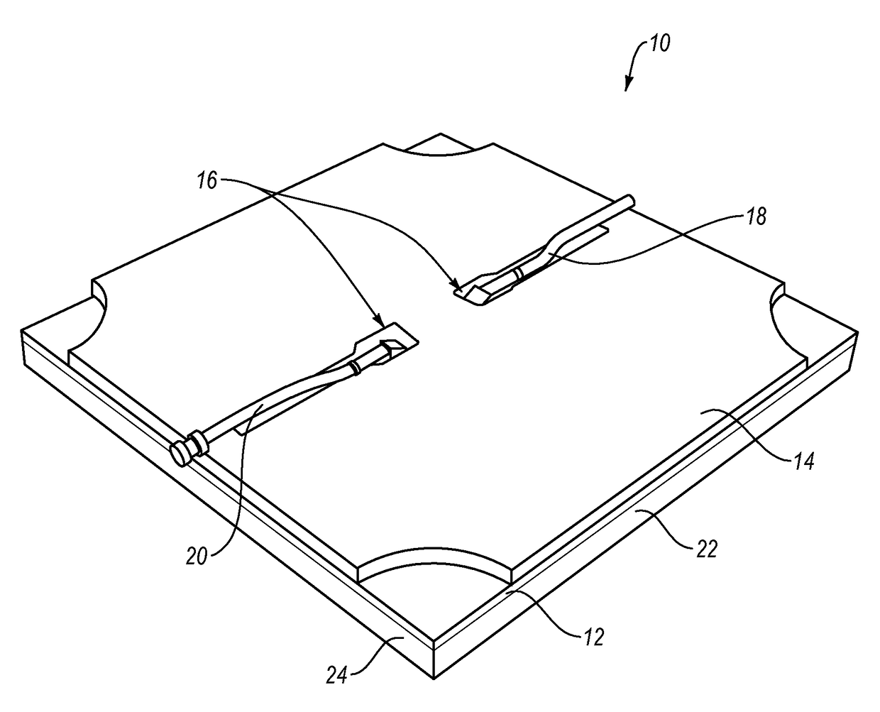
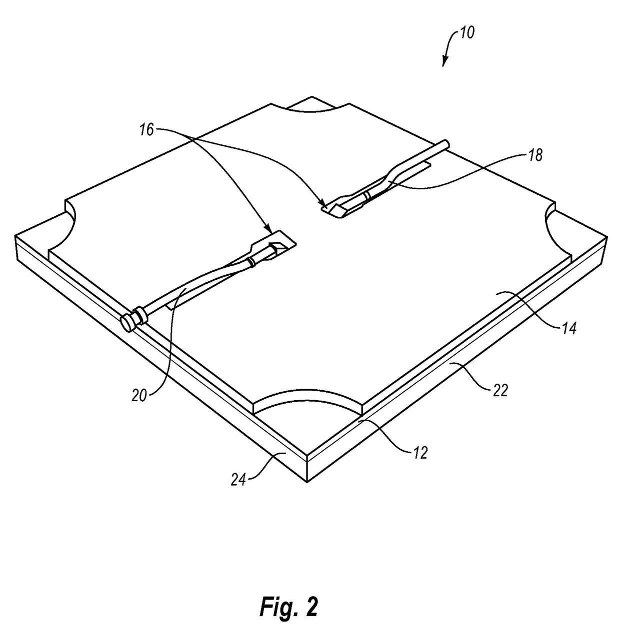
[0036]One or more implementations of the present invention are directed to systems, methods, and apparatus that create many new opportunities for the use of thermal transfer between fluids and a thermal mass. In particular, one or more implementations include modular thermal transfer panels with simple, yet efficient designs. In one or more implementations, the modular thermal panels can function as invisible solar collectors.

[0037]Implementations of the present invention can include modular thermal panels made of thermal conductive material (e.g., aluminum) with channels formed inside. One or more thermal masses (i.e., an architectural tile) can cover the thermal panels. A thermal exchange fluid circulating through the channels can absorb from or transfer heat to the architectural tiles.

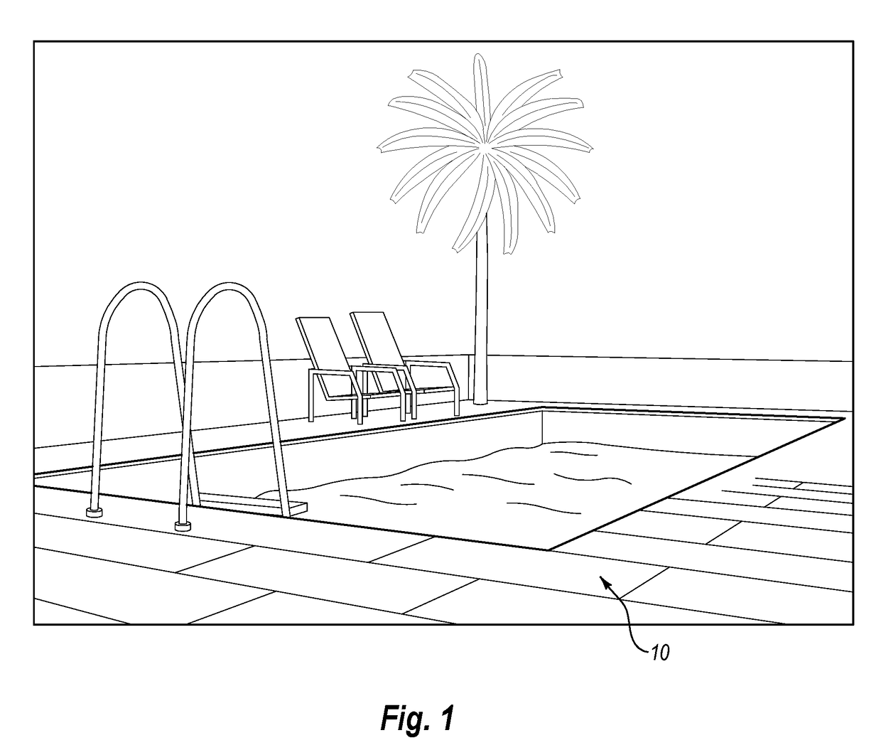
[0038]Modular thermal panels of the present invention can have various different uses. For example, it is common for flat roofed buildings, plazas and patios to have paver / slabs installed on pedesta...


PUM


Abstract

A modular thermal panel can include a heat exchanger having connected top and bottom plates with channels formed there between for receiving a heat exchange fluid. An architectural tile (e.g., a paver, stone, acoustic tile, or any other architectural element) can rest on the top of the modular thermal panel, while an insulator panel is positioned below the modular thermal panel. The heat exchanger can transfer heat between the architectural tile and the heat exchange fluid to either cool or heat the architectural panel. Additional implementations include heat transfer systems including such modular thermal panels, and methods of collecting and utilizing thermal energy using such modular thermal panels.

Description

CROSS-REFERENCE TO RELATED APPLICATIONS[0001]The present application is a 35 U.S.C. §371 U.S. National Stage of PCT Application No. PCT / US2012 / 039008 filed May 22, 2012, entitled, “MODULAR, FLUID THERMAL TRANSFER DEVICE,” which claims priority to U.S. patent application Ser. No. 13 / 117,098, filed May 26, 2011, entitled “MODULAR, FLUID THERMAL TRANSFER DEVICE.” The entire contents of each of the aforementioned patent applications is incorporated by reference herein.BACKGROUND OF THE INVENTION[0002]1. Technical Field[0003]The present invention relates to apparatus, systems, and methods for transferring thermal energy. More particularly, implementations of the present invention relate to apparatus, systems, and methods for transferring thermal energy between an object and a fluid contained and transited within a heat exchanger. More specifically, one or more implementations of the present invention relate to a modular heat exchange panels that can be easily connected and disconnected w...

Claims


Application Information

Patent Timeline
Patent Type & Authority Patents(United States)
IPC IPC(8): F24J2/04E04C2/52F24D3/14E04B9/04F24D3/12F24D3/16
CPCF24J2/0422E04B9/0421E04B9/0464E04C2/525F24D3/122F24D3/125F24D3/127F24D3/14F24D3/142F24D3/16F24J2/0438Y02B10/20Y02E10/44F24S20/60F24S20/64Y02B30/00Y02E10/40
Inventor BARMORE, ROBERT P.
Owner THERMA HEXX
Why Eureka
Try Eureka