
Thermoplastic component repair

a technology applied in the field of thermoplastic parts and components repair, can solve the problems of limited damage and parts may sustain damage in manufacture, and achieve the effects of convenient access, flexible and controllable techniques, and easy reconfigurability

Active Publication Date: 2017-06-27
GM GLOBAL TECH OPERATIONS LLC
View PDF15 Cites 69 Cited by
  • Summary
  • Abstract
  • Description
  • Claims
  • Application Information

AI Technical Summary

Benefits of technology

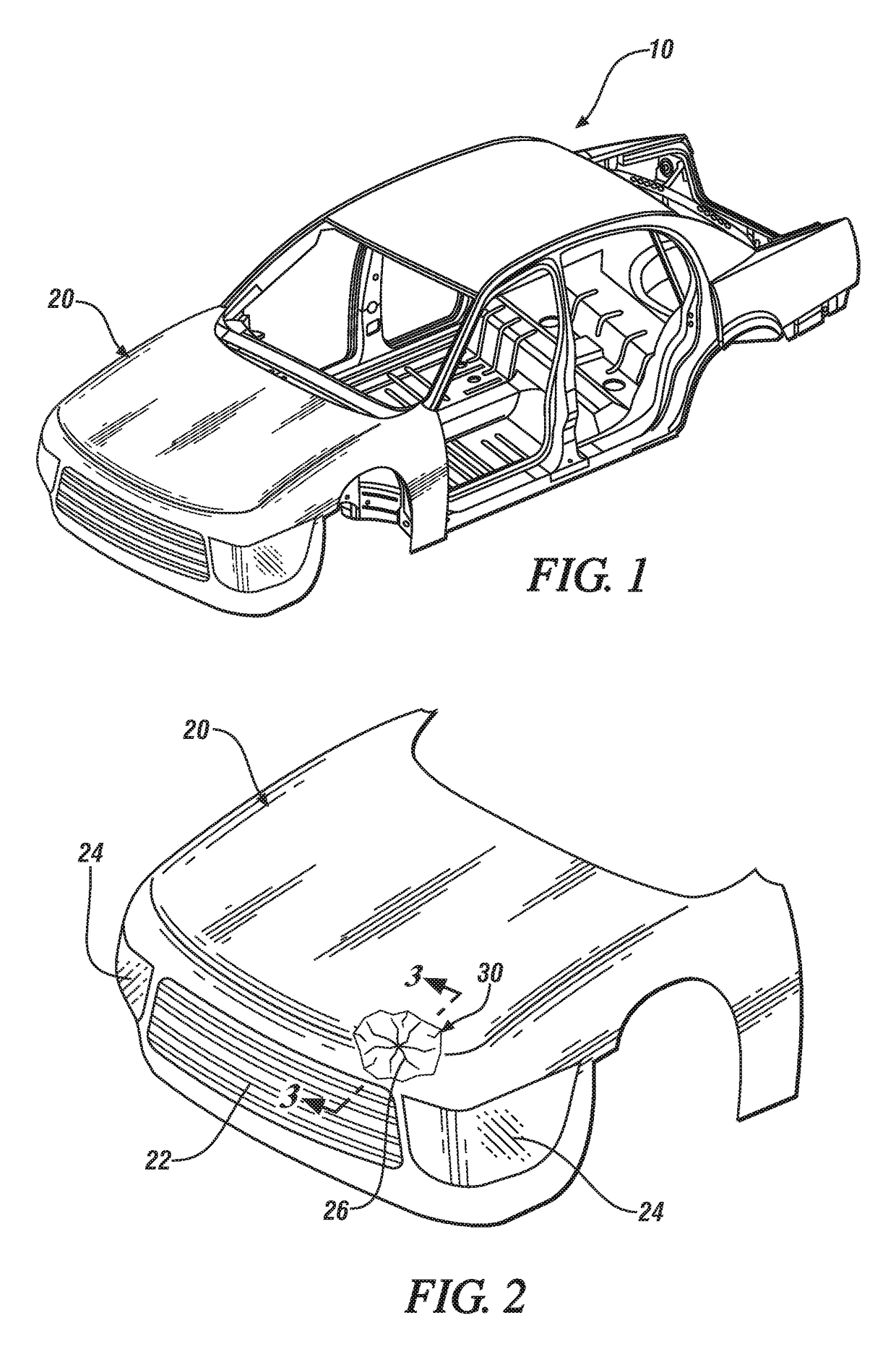
[0008]Such parts may sustain damage in manufacture, during installation or assembly into a vehicle, device or machine, or when placed in service. Often, such damage will be of limited extent and confined to only some region of the component. This invention provides a method for repair of such damaged thermoplastic parts. The method may be practiced with the component removed from the vehicle device or machine or in-place, thereby eliminating or minimizing any need for disassembly to remove the damaged component prior to repair.
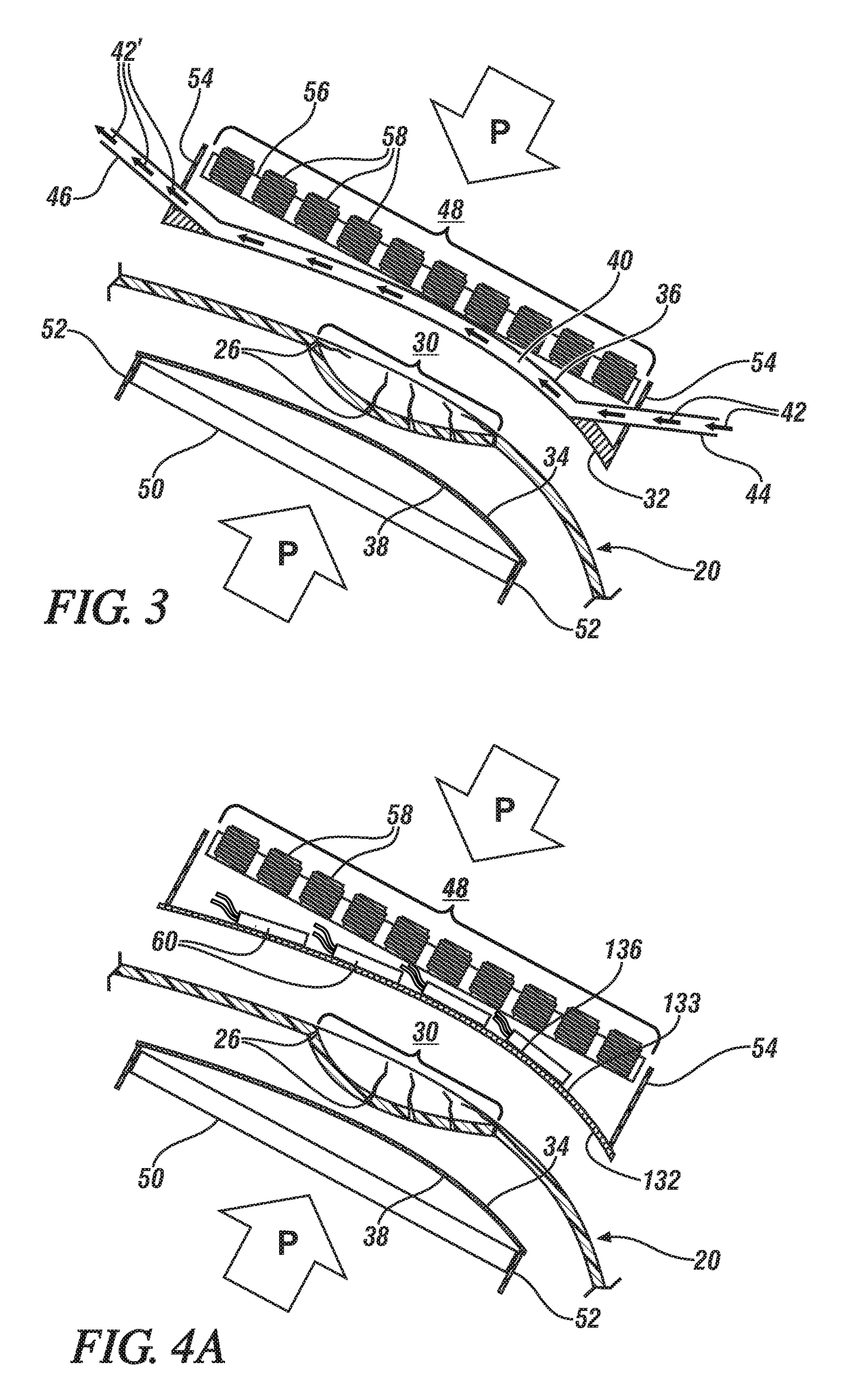
[0011]Typically suitable repair temperatures for thermoplastics employed in automobiles and light duty trucks may vary significantly. Suitable temperatures may be 150-210° C. for thermoplastic Nylon (polyamide), 100-170° C. for thermoplastic polyolefin and 220-280° C. for thermoplastic polyesters. Heating will be confined to the damaged region so that only the damaged region experiences a sufficiently elevated temperature to soften and / or melt the component. The die portions extend beyond the damaged portion and because only the damaged portion is heated to a melting or reflow temperature, the softened or melted portion will be confined on its faces by the contacting, pressurized die portions and on its periphery by the undamaged, cooler, stronger portion of the component. Thus no loss of the thermoplastic due to expulsion during repair may occur. The reflow or melting process will serve to fuse together the surfaces of any defects, for example opposing crack surfaces, in the damage zone together, so that the damage to the thermoplastic may be undone. The part may then be cooled, maintaining the die portions in place and under pressure until the part temperature is reduced below the melting point of the thermoplastic, at which temperature the die shell portions may be removed. Thus, the part may be reshaped and substantially restored to its original form, appearance and functionality.
[0019]Induction heating may also be used with metal mold portions. A suitably-shaped coil spaced apart from the metal mold portion and electrically excited by high frequency alternating current, say at frequencies of between 5 and 100 kHz will induce eddy currents in the opposing surface of the mold portion resulting in heating due to resistive losses. By suitably matching the frequency of the alternating current with the thickness of the mold portions heat may be generated though the thickness of the mold portion reducing the need for a highly thermally conductive mold portion to facilitate heat transfer from the opposing side to the component-contacting surface of the mold portion.
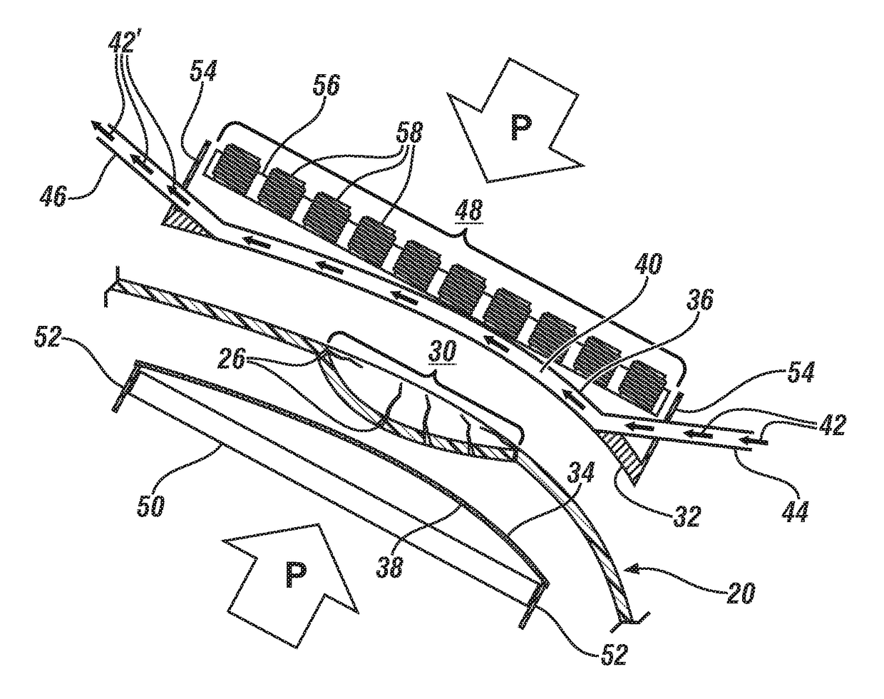
[0021]As noted previously it is preferred to maintain a preselected pressure of between about 7 and 700 kPa on the die portions during the reflow or melting process. Depending on the specific thermoplastic, the local component geometry and thickness in the damaged area and the extensiveness of the damage, the force required to develop such a pressure may vary by at least the 100:1 pressure range. The pressure may be applied by two pressure pads comprising magnetic elements arranged to magnetically attract one another and so develop the required pressure. The magnetic elements may be magnets or electromagnets, or one of the elements may be ferromagnetic body. The ferromagnetic body may be a die portion or a separate component. The pressure pads may be located outboard of the die portions so that the die portions are positioned between the magnetic entities and the component. Compared to clamps or other such purely mechanical approaches, this magnetic approach facilitates access to the unexposed surface of the component since attraction is exerted directly between the opposing magnetic entities, and no external mechanical support such as clamps or posts need be provided.
[0022]If permanent magnets are used, developing variable force may necessitate adding and removing magnets as required, an approach which will generally admit of only discrete changes in magnetic force. A more flexible and controllable technique is to use electromagnets. Then, through modeling or experimentation, the required force may be preselected by selection of the current passed through the electromagnets. For maximum flexibility the electromagnets may be mounted on a rack and readily reconfigurable and / or the currents passed through each electromagnet, or, more likely, through selected groups of electromagnets, may be adjusted to achieve a desired magnetic field.
[0023]For ease of operation it may be preferred to employ electromagnets on only one side, generally the more accessible side, and to locate the more compact and maneuverable ferromagnetic body on the less accessible side. For ease of handling, it may be convenient to fabricate the die portions for easy, temporary, attachment of the magnet frame or ferromagnetic body to the mold portion. For example the mold body, on its opposing surface may accommodate a pocket with threaded bolt holes so that it may receive the magnetic pressure pad and removably secure it with bolts.

Problems solved by technology

Such parts may sustain damage in manufacture, during installation or assembly into a vehicle, device or machine, or when placed in service.
Often, such damage will be of limited extent and confined to only some region of the component.

Method used


Image

  • Thermoplastic component repair
  • Thermoplastic component repair
  • Thermoplastic component repair

Examples


Embodiment Construction

[0033]The following description of the embodiment(s) is merely exemplary in nature and is not intended to limit the invention, its application, or uses.

[0034]One ‘lightweighting’ strategy employed by vehicle manufacturers is to replace mass-intensive sheet steel components with lighter weight polymer components, commonly higher strength, fiber reinforced polymer components.

[0035]Initially most such polymer-based components were manufactured of thermosetting polymers, or thermosets, but, increasingly, thermoplastic polymers, or thermoplastics are being used.

[0036]An advantage enjoyed by thermoplastics over thermosets is that thermoplastics, once formed, may be re-heated to about their melting point, softened and remelted and then reshaped by application of pressure. Provided the reheating temperature is controlled and limited to only modestly exceeding the polymer melting point, such reshaping may be performed without appreciably degrading the properties of the polymer. This characte...


PUM

PropertyMeasurementUnit
thicknessaaaaaaaaaa
pressureaaaaaaaaaa
pressureaaaaaaaaaa

Abstract

Thermoplastic components may experience local damage, including cracks and decohesion of fiber reinforcements, among others. Such thermoplastics may be repaired by heating them to a suitable softening / melting temperature under pressure and maintaining them under pressure and at elevated temperature until the damage is healed. This may be done in-place using custom-fabricated, suitably-shaped die portions maintained under pressure by magnetic attraction. Various heating methods and die portion fabrication methods are described.

Description

TECHNICAL FIELD[0001]This invention pertains to methods of repairing thermoplastic parts and components, optionally containing fillers or reinforcements, particularly in-place repair after their assembly into a vehicle, device or machine.BACKGROUND OF THE INVENTION[0002]In automotive body construction there is an increasing trend to use lightweight materials, or materials which offer higher structural performance per unit mass than low carbon or ‘mild’ steel, historically the material of choice for automobile bodies. A broad range of light-weight materials is currently in use including high strength steel, alloys of metals with lower density than steel, for example aluminum and magnesium, and polymers and polymer composites.[0003]The initial use of polymers and polymer composites employed thermosetting polymers but, increasingly, attention is being focused on thermoplastic polymers which are beginning to supplant some of the earlier-adopted, alternative materials used in automobile ...

Claims


Application Information

Patent Timeline
Patent Type & Authority Patents(United States)
IPC IPC(8): B29C33/32B29C73/30B29C35/08B29C35/02B29C35/04B29C73/34
CPCB29C73/30B29C35/041B29C73/34B29C2035/0211B29C2035/0811B29C2035/0816B29K2995/0008
Inventor KIA, HAMID G.HUANG, XIAOSONG
Owner GM GLOBAL TECH OPERATIONS LLC
Learn More