Worm speed reducer and method for manufacturing worm wheel included in worm speed reducer

a technology of worm speed reducer and worm shaft, which is applied in the direction of worm wheels, gearing, hoisting equipment, etc., can solve the problems of tooth hitting sound (rattle sound) and needing backlash between the worm shaft and the worm wheel, and achieve the effect of suppressing the difference in frictional resistance torqu

Active Publication Date: 2017-06-27
JTEKT CORP
View PDF8 Cites 7 Cited by
  • Summary
  • Abstract
  • Description
  • Claims
  • Application Information

AI Technical Summary

Benefits of technology

[0010]An object of the present invention is to provide an inexpensive worm speed reducer that enables suppression of a difference in frictional resistance torque due to a difference in rotating direction and a method for manufacturing a worm wheel included in the worm speed reducer.

Problems solved by technology

The meshing between the worm shaft and the worm wheel needs backlash.
However, during traveling, tooth hitting sound (rattle sound) may occur due to the backlash.

Method used


Image

  • Worm speed reducer and method for manufacturing worm wheel included in worm speed reducer
  • Worm speed reducer and method for manufacturing worm wheel included in worm speed reducer
  • Worm speed reducer and method for manufacturing worm wheel included in worm speed reducer

Examples


Embodiment Construction

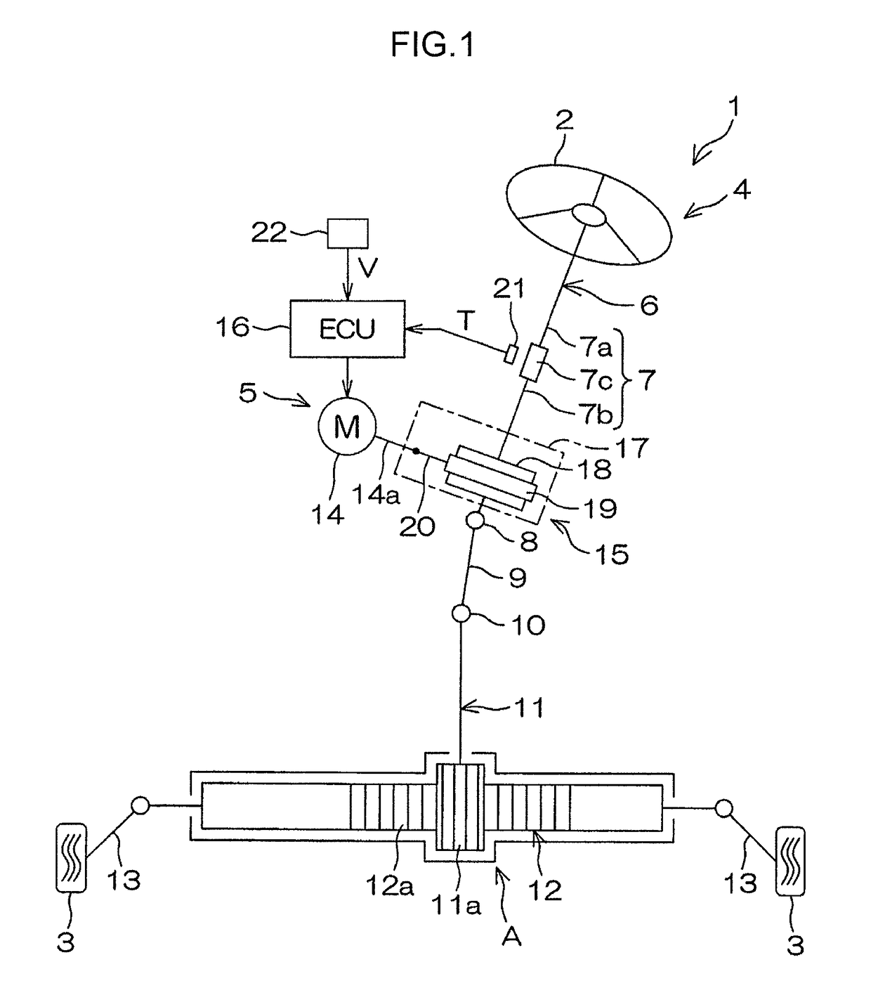
[0023]An embodiment of the present invention will be described below in accordance with the drawings. FIG. 1 is a schematic diagram depicting a general configuration of an electric power steering system including a worm speed reducer according to an embodiment of the present invention. As depicted in FIG. 1, an electric power steering system 1 includes a steering mechanism 4 and an assist mechanism 5. The steering mechanism 4 turns turning wheels 3 based on a driver's operation of a steering wheel 2 (steering member). The assist mechanism 5 assists the driver's steering operation.

[0024]The steering mechanism 4 includes a steering shaft 6 that serves as a rotating shaft of the steering wheel 2. The steering shaft 6 includes a column shaft 7, an intermediate shaft 9, and a pinion shaft 11. The column shaft 7 is coupled to a center of the steering wheel 2. The intermediate shaft 9 is coupled to one end (axially lower end) of the column shaft 7 via a universal joint 8. The pinion shaft ...


PUM


Abstract

A plane that contains a central axis of a worm shaft and that is orthogonal to a central axis of a worm wheel is arranged at a central position of the worm wheel in a tooth width direction thereof when no load is applied to a worm speed reducer. The worm wheel is formed by a cutting operation using a hob with a hob center offset from the central position toward an offset direction corresponding to a first direction along the tooth width direction. A pair of tooth flanks has different pressure angles at the central portion in the tooth width direction.

Description

INCORPORATION BY REFERENCE[0001]The disclosure of Japanese Patent Application No. 2014-134840 filed on Jun. 30, 2014 including the specification, drawings and abstract, is incorporated herein by reference in its entirety.BACKGROUND OF THE INVENTION[0002]1. Field of the Invention[0003]The present invention relates to a worm speed reducer and a method for manufacturing a worm wheel included in the worm speed reducer.[0004]2. Description of Related Art[0005]In an electric power steering system, rotation output from an electric motor is transmitted to a worm shaft in a worm speed reducer. The rotation output from the electric motor is decelerated via a worm wheel that meshes with the worm shaft, and the resultant rotation is transmitted to a turning mechanism. Thus, a steering operation undergoes torque assistance. The meshing between the worm shaft and the worm wheel needs backlash. However, during traveling, tooth hitting sound (rattle sound) may occur due to the backlash.[0006]Conseq...

Claims


Application Information

Patent Timeline
Patent Type & Authority Patents(United States)
IPC IPC(8): F16H1/16F16H55/22B23F11/00F16H55/02F16H55/24
CPCF16H1/16B23F11/00F16H55/22F16H55/24
Inventor HAMAKITA, JUN
Owner JTEKT CORP
Why Eureka
Try Eureka