Display device having in-cell touch structure and method of driving the same

a technology of in-cell touch and display device, which is applied in the direction of instruments, computing, electric digital data processing, etc., can solve the problems of increasing reducing generating unsatisfactory parasitic capacitance, so as to reduce the accuracy of touch sensing, prevent parasitic capacitance, and increase the load of touch operation

Active Publication Date: 2017-06-27
LG DISPLAY CO LTD
View PDF27 Cites 8 Cited by
  • Summary
  • Abstract
  • Description
  • Claims
  • Application Information

AI Technical Summary

Benefits of technology

[0013]Various aspects of the present invention provide a display device having an in-cell touch structure and a method of driving the same able to prevent parasitic capacitance that would otherwise increase the load of a touch operation, lower the accuracy of touch sensing, or disable touch sensing.

Problems solved by technology

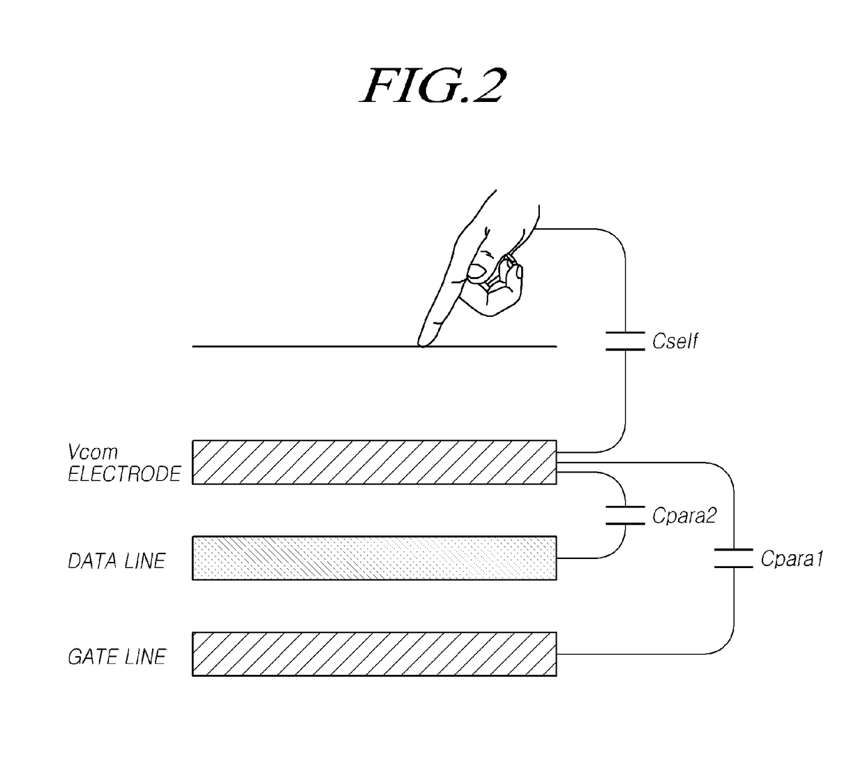
According to capacitive touch sensing technology, in addition to capacitance necessary for touch sensing, undesirable parasitic capacitance is generated by other voltage lines or electrodes surrounding touch electrodes.
Such undesirable parasitic capacitance causes certain problems, for example, increasing the load of a touch operation, decreasing the accuracy of touch sensing, and in severe cases, making touch sensing impossible.
The problems caused by parasitic capacitance become more severe in medium-sized or larger display devices.
The problems caused by the undesirable parasitic capacitance frequently occur in in-cell display devices inside which a touchscreen panel (TSP) is integrally provided using “in-cell” technology, even causing the realization of medium-sized or larger in-cell touchscreen panels to be impossible.

Method used


Image

  • Display device having in-cell touch structure and method of driving the same
  • Display device having in-cell touch structure and method of driving the same
  • Display device having in-cell touch structure and method of driving the same

Examples


Embodiment Construction

[0062]Reference will now be made in detail to embodiments of the present invention, examples of which are illustrated in the accompanying drawings. Throughout this document, reference should be made to the drawings, in which the same reference numerals and signs will be used to designate the same or like components. In the following description of the present invention, detailed descriptions of known functions and components incorporated herein will be omitted in the case that the subject matter of the present invention may be rendered unclear thereby.

[0063]It will also be understood that, although terms such as “first,”“second,”“A,”“B,”“(a)” and “(b)” may be used herein to describe various elements, such terms are only used to distinguish one element from another element. The substance, sequence, order or number of these elements is not limited by these terms. It will be understood that when an element is referred to as being “connected to” or “coupled to” another element, not only...


PUM


Abstract

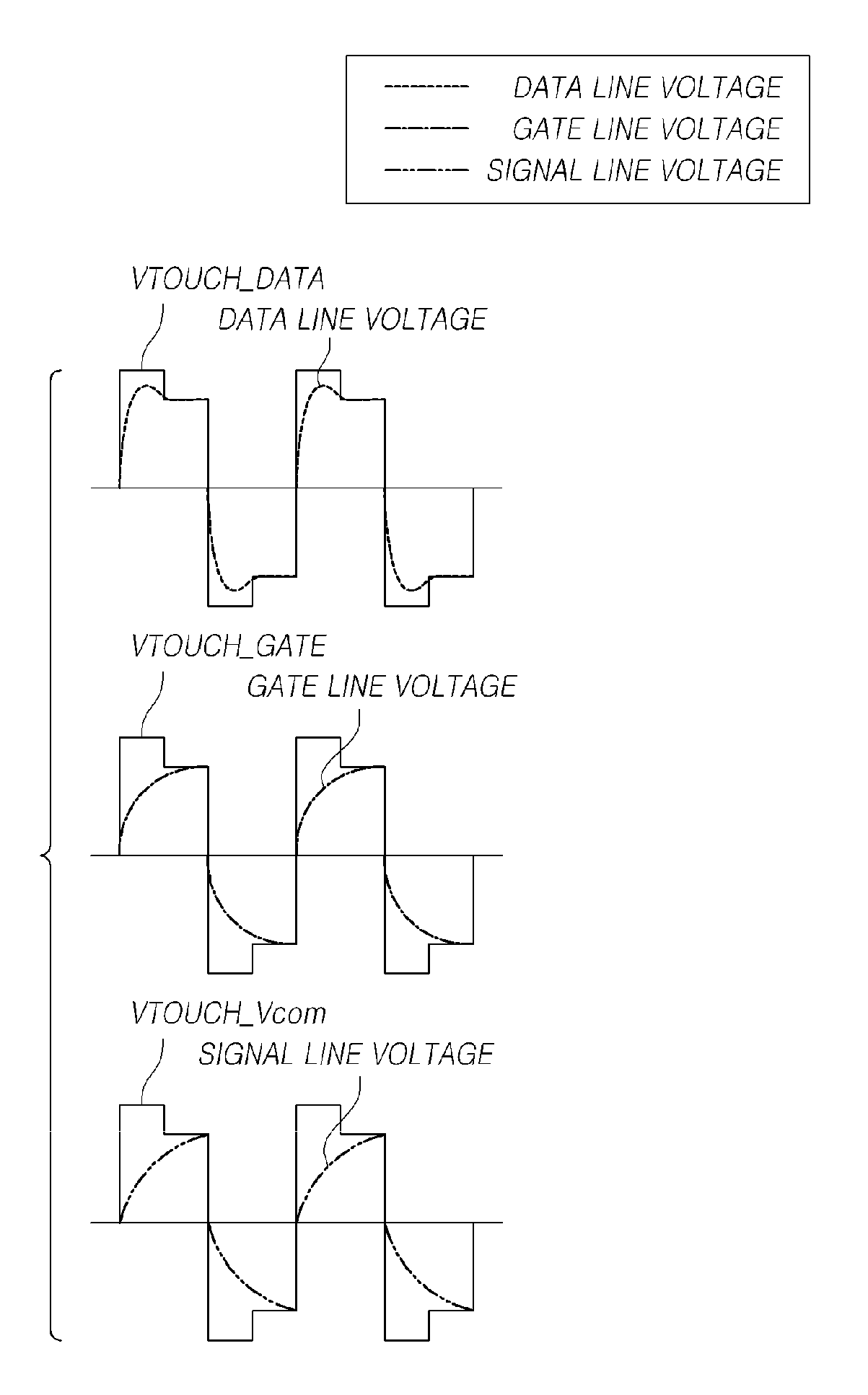
A display driver circuit comprises first circuitry to generate a touch drive signal, and second circuitry to provide the touch drive signal to touch sense electrodes of the display device and a touch data signal to data lines of the display device during a touch period and to provide display data signals to data lines of the display device during a display period. A touch gate signal is provided to gate lines of the display device during the touch period. The touch drive signal, the touch data signal, and the touch gate signal mimic a reference waveform, but amplitudes of one or more of the touch drive signal, the touch data signal, and the touch gate signal are overdriven by their respective overdrive amplitude with respect to the reference waveform during their respective overdrive duration.

Description

BACKGROUND OF THE INVENTION[0001]Field of the Invention[0002]The present invention relates to a display device having an in-cell touch structure and a method of driving the same.[0003]Description of Related Art[0004]In response to the development of the information society, there is increasing demand for various types of display devices able to display images. Currently, a range of display devices, such as liquid crystal display (LCD) devices, plasma display panels (PDPs) and organic light-emitting diode (OLED) display devices, are in common use.[0005]Many display devices provide a touch-based input system enabling users to intuitively and conveniently input data or instructions directly to a device screen, rather than using conventional input systems, such as buttons, a keyboard, or a mouse.[0006]In order to provide such a touch-based input system, sensitivity to the touch of a user and the ability to accurately detect coordinates of a touch point are required.[0007]In this regard,...

Claims


Application Information

Patent Timeline
Patent Type & Authority Patents(United States)
IPC IPC(8): G06F3/044G09G5/00
CPCG06F3/044G09G5/003G09G2300/0426G09G3/20G09G2354/00G06F3/0446G06F3/04166
Inventor SHIN, SEUNGROKJUNG, JIHYUNLEE, DEUKSUKIM, TAEYUN
Owner LG DISPLAY CO LTD
Why Eureka
Try Eureka