Natural rock panel, natural rock veneer panel and panel support apparatus

a technology of natural rock veneer and supporting apparatus, which is applied in the direction of walls, building components, construction materials, etc., can solve the problems of releasing one of more stone elements from the structure, time-consuming installation of this type of element, and affecting the appearance of mortar joints

Inactive Publication Date: 2017-07-04
PACIFIC PREBENCHED
View PDF158 Cites 7 Cited by
  • Summary
  • Abstract
  • Description
  • Claims
  • Application Information

AI Technical Summary

Benefits of technology

[0027]In accordance with another aspect of the invention, there is provided an architectural finishing method. The method involves mounting a mounting portion of a body of at least one dual architectural finish element support to a surface of an architectural structure, and causing a first holder on the body to hold a portion of a bottom edge of a first architectural finish element in a first holder. The method also involves causing a second holder on the body to hold a portion of a top edge of a second architectural finish element adjacent to the bottom edge of the first architectural finish element and in alignment with the bottom edge of the first architectural finish element such that finish surfaces of the first and second architectural finish elements are generally coplanar. The method also involves causing the body to absorb mechanical forces between the first and second architectural finish elements and the architectural structure.

Problems solved by technology

Installation of this type of element is time-consuming, and such elements can be susceptible to release from the surface due to thermal expansion and contraction, which can loosen mortar adhesion systems that secure such elements to an architectural structure for example.
Further, such individually secured stone elements are often joined by mortar joints having thicknesses of about ⅜ inches or more, and such mortar joints may have an undesirable appearance.
Some inventors have overcome the mortar adhesion problem by cutting grooves into the individual stone elements and using a support clip that cooperates with the groove to support the individual stone element, but this tends to secure the stone elements rather rigidly to the surface of the architectural structure, which can still be a problem due to wind loading and seismic loading.
Forces due to these conditions can result in displacement of the individual stone elements from the clips, resulting in release of one of more of the stone elements from the structure.
Generally, individual stone elements are not aggregated together into unitary collections to form an architectural finish element because the stone elements themselves are generally relatively heavy such that any unitary collection of stone elements is generally too heavy to be lifted by a single person and would be too heavy to meet many building codes.
To reduce weight, individual stone elements may sometimes be secured to a foam backing for example, but the foam can deform over time if subjected to point loading and can be susceptible to ultraviolet radiation degradation and can present challenges for fire proofing.
Artificially formed surfaces comprised of concrete painted and molded to look like a dry-stacked arrangement of individual stone elements have been used on foam to form building blocks but are still too heavy and therefore not suitable for cladding a building.
Patio and walkway surfaces have been paved by masonry panels comprising a reinforced series of masonry elements such as stone or brick pavers bound together by a cement or mortar-like material, but these too are too heavy for cladding an architectural structure.

Method used


Image

  • Natural rock panel, natural rock veneer panel and panel support apparatus
  • Natural rock panel, natural rock veneer panel and panel support apparatus
  • Natural rock panel, natural rock veneer panel and panel support apparatus

Examples


Embodiment Construction

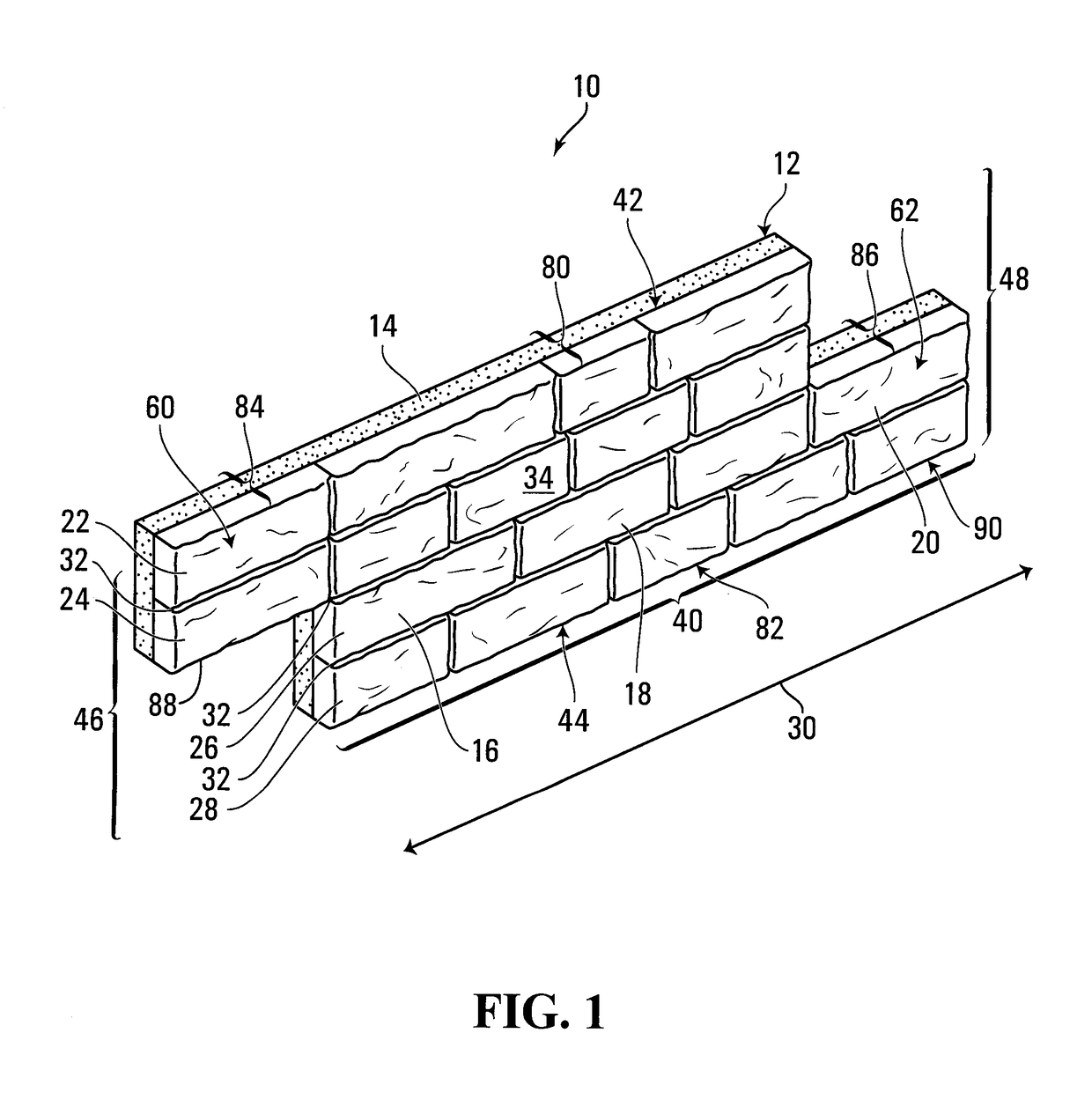
[0094]Referring to FIG. 1, an architectural finish element operable to be placed adjacent similar architectural finish elements to form a finished surface on an architectural structure is shown generally at 10. The architectural finish element 10 is in the form of a panel and comprises a body 12 formed of a rock-based composite material comprising a low density solid particle additive 14 and a plurality of unitary real stone veneer elements, such as shown at 16, 18 and 20 for example, bonded to the body.

[0095]In this embodiment, the rock-based composite material forming the body 12 is comprised of Portland cement mixed with water and an aggregate comprised of pumice in a ratio of 1.5:1:2. In this embodiment, the veneer elements, such as shown at 16, 18 and 20 for example, may be bonded to the body 12 by casting the body adjacent the veneer elements.

[0096]The solid particle additive 14 may be recycled waste, non-toxic waste, post manufacturing waste, or post consumer waste, for examp...


PUM


Abstract

An architectural finish element operable to be placed adjacent similar architectural finish elements to form a finished surface on an architectural structure includes a body formed of a rock-based composite material comprising a low density solid particle additive, a plurality of unitary real stone veneer elements bonded to the body in courses extending in a first direction and in a random non-repetitive pattern, the real stone veneer elements having respective face surfaces generally lying in a plane to form an overall face surface of the architectural finish element. The low density solid particle additive is provided in an amount suitable to cause the architectural finish element to have a density of between about 10 to 15 pounds per square foot. The architectural finishing element may be mounted by mounting a portion of a body of at least one dual architectural finish element support to a surface of an architectural structure.

Description

CROSS REFERENCE TO RELATED APPLICATIONS[0001]This application is the U.S. National Phase of International Application No. PCT / CA2012 / 000355, filed Apr. 18, 2012, designating the U.S. and published as WO / 2012 / 149630 on Nov. 8, 2010 which claims the benefit of U.S. Provisional Patent Application No. 61 / 481,681, filed May 2, 2011.BACKGROUND OF THE INVENTION[0002]1. Field of Invention[0003]This invention relates to architectural finish elements and supporting apparatus therefor, and more particularly to architectural finish elements that employ real rock configured in a lightweight panel form. The invention also relates to apparatus for supporting architectural finish panels including the type that employ real rock configured in a lightweight panel form.[0004]2. Description of Related Art[0005]Various architectural finish elements have been used over the years to clad architectural structures such as buildings. Some of these architectural finish elements involve individual stone element...

Claims


Application Information

Patent Timeline
Patent Type & Authority Patents(United States)
IPC IPC(8): E04B2/72E04F13/09E04C2/38E04C2/288E04F13/00E04F13/08E04F13/14E04C2/28E04B2/02E04C2/00
CPCE04F13/007E04B2/721E04C2/288E04C2/38E04F13/0801E04F13/0846E04F13/0878E04F13/0885E04F13/0892E04F13/0894E04F13/09E04F13/14E04F13/144E04B2002/0269E04B2002/0271E04C2002/008E04F2201/026Y10T428/192
Inventor MCINTOSH, ROBERT GORDONNEMEZ, BRIAN PHILIP
Owner PACIFIC PREBENCHED
Why Eureka
Try Eureka