
Variable property electrodepositing of metallic structures

a technology of metallic structures and variable properties, applied in the direction of electrolytic coatings, ion implantation coatings, air transportation, etc., can solve the problems of increased capital equipment, increased processing costs, and increased floor spa

Active Publication Date: 2009-06-25
INTEGRAN TECH
View PDF39 Cites 107 Cited by
  • Summary
  • Abstract
  • Description
  • Claims
  • Application Information

AI Technical Summary

Benefits of technology

[0008]Of special interest is that the variable property deposit is prepared in a single plating tank. In the past, i.e., layered structures of different composition but with uniform properties in the layer were obtained by using several plating tanks each containing a dedicated electrolyte and without varying the plating conditions. The workpiece was simply moved from one tank to the next, with repetitive washing steps in between, to effect the property change. The disadvantage of this approach is increased floor space, increased capital equipment and increased processing cost due to the cost of water purification and disposal for the wash water. An added cost / risk is cross contamination particularly with complex parts which may form cups etc. entrapping electrolyte which cannot be easily removed by washing steps significantly increasing the bath maintenance and overall operating cost.

Problems solved by technology

The disadvantage of this approach is increased floor space, increased capital equipment and increased processing cost due to the cost of water purification and disposal for the wash water.
An added cost / risk is cross contamination particularly with complex parts which may form cups etc. entrapping electrolyte which cannot be easily removed by washing steps significantly increasing the bath maintenance and overall operating cost.

Method used


Image

  • Variable property electrodepositing of metallic structures
  • Variable property electrodepositing of metallic structures
  • Variable property electrodepositing of metallic structures

Examples


working example i

Grading of Ni Electrodeposit to Grade Grain Size and Hardness in the Deposit Direction with Electrodeposition Condition Modulation

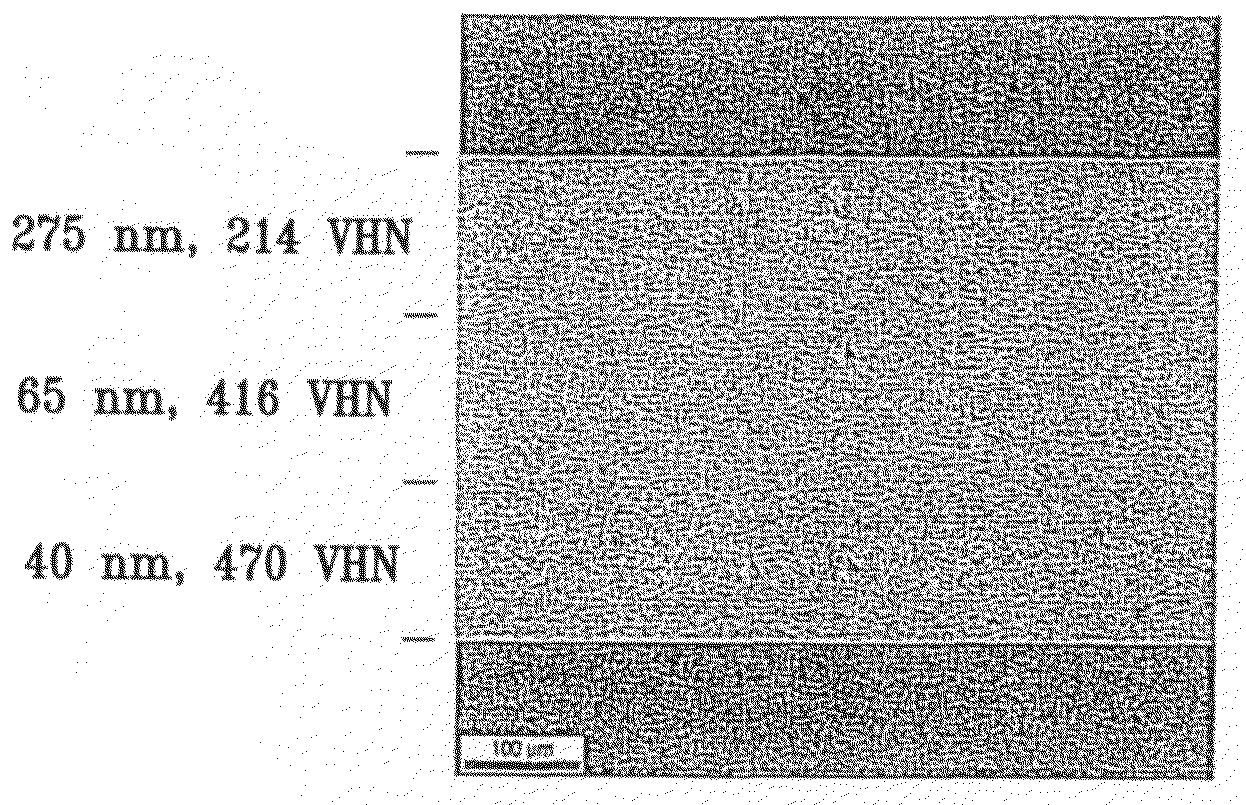
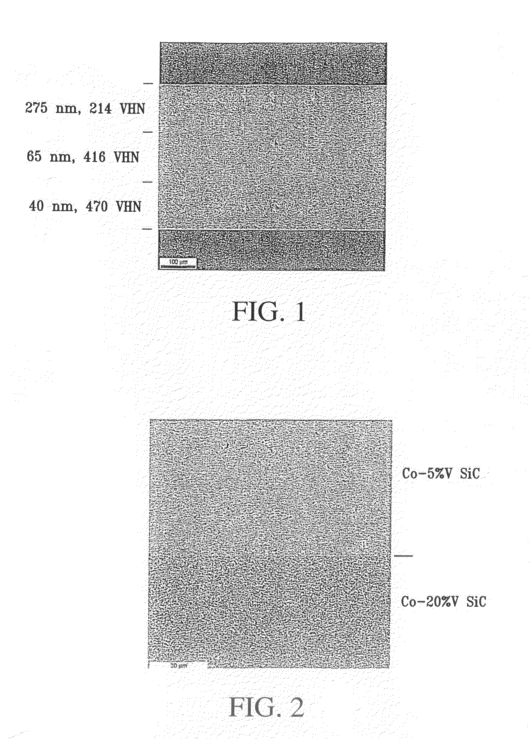
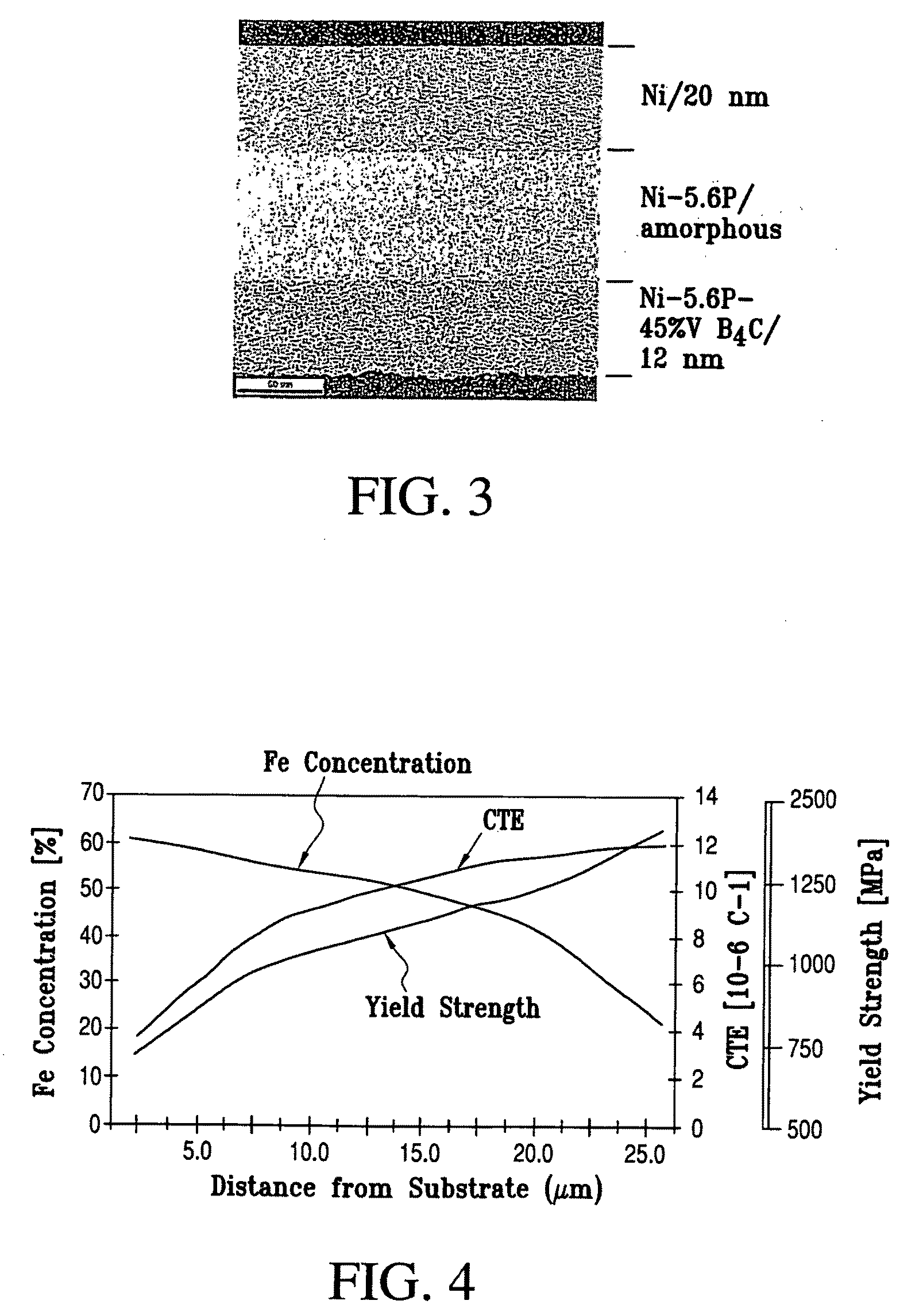
[0135]Free-standing Ni-layers with variable property and multilayered grain size were electrodeposited on a polished Ti cathode (10 cm2) in a modified Watts nickel bath (40 1 tank) using grain refiners, levelers, brighteners, stress relievers and chelating agents (Integran Technologies Inc., Toronto, Ontario, Canada). Nickel “R”-rounds (Inco Ltd., Sudbury, Ontario, Canada) were used as anode material. NPA-91 is provided by Atotech USA (Rock Hill, S.C.). The plating current was supplied by a Dynatronix (Amery, Wis., USA, Dynanet PDPR 40-100-400) pulse power supply. The electrolyte and the electroplating conditions used are indicated in Table 2. The variation in grain size of the metallic layers was achieved by modulating the electroplating conditions as set forth in Table 2. Resulting variable property structure is shown in FIG. 1. FIG. 1 shows a cross-sec...

working example ii

Variable Property Nano-Ni—Fe Electrodeposit to Simultaneously Grade Deposit Chemical Composition and Grade Grain Size in the Deposit Direction with Current Density Modulation

[0137]Aluminum open-cell porous foam blocks 2×0.5×1″ (20 pores per inch, ERG Materials and Aerospace Corp., Oakland, Calif., USA) were filled by coating with fine-grained Ni—Fe by placing the foam substrates as cathodes in a plastic frame to expose the frontal area only to the electrolyte and subjected to the plating conditions indicated in Table 3. A modified Watts nickel bath adapted for Ni—Fe alloy plating (Integran Technologies Inc., Toronto, Ontario, Canada) was placed in a 40 liter tank and a Dynatronix (Amery, Wis., USA, Dynanet PDPR 40-100-400) pulse power supply was employed. The electrolyte composition used is provided in Table 3 below. A soluble Ni anode was employed (Inco Ltd., Sudbury, Ontario, Canada) and the Fe concentration replenished continuously at a rate to maintain the Fe concentration const...

working example iii

Electrodepositing Variable Property Nanocrystalline-Ni—Fe Electrodeposit on Graphite / Epoxy Golf Shaft with Cathode Rotational Speed Modulation

[0139]A graphite / epoxy golf shaft with an outer diameter of about ½″ was placed on a suitable mandrel. The mandrel was inserted in a rotator equipped with a variable rotation speed motor, submersed into the electrolyte and subjected to the plating conditions indicated in Table 4. The modified Watts nickel bath outlined in Working Example II adapted for Ni—Fe alloy plating (Integran Technologies Inc., Toronto, Ontario, Canada) was placed in a 40 liter tank and a Dynatronix (Amery, Wis., USA, Dynanet PDPR 40-100400) pulse power supply was employed. Soluble Ni-rounds (Inco Ltd., Sudbury, Ontario, Canada) and electrolytic Fe rounds (Allied Metals Corp. of Troy, Mich.) were employed as anodes. NPA-91 is provided by Atotech USA (Rock Hill, S.C.). The golf club shaft was the cathode. The plating conditions were varied, to continuously vary the alloy ...


PUM

PropertyMeasurementUnit
Lengthaaaaaaaaaa
Lengthaaaaaaaaaa
Fractionaaaaaaaaaa

Abstract

Variable property deposit, at least partially of fine-grained metallic material, optionally containing solid particulates dispersed therein, is disclosed. The electrodeposition conditions in a single plating cell are suitably adjusted to once or repeatedly vary at least one property in the deposit direction. In one embodiment denoted multidimension grading, property variation along the length and / or width of the deposit is also provided. Variable property metallic material deposits containing at least in part a fine-grained microstructure and variable property in the deposit direction and optionally multidimensionally, provide superior overall mechanical properties compared to monolithic fine-grained (average grain size: 2 nm-5 micron), entirely coarse-grained (average grain size: >20 micron) or entirely amorphous metallic material deposits.

Description

TECHNICAL FIELD[0001]The invention is directed to DC or pulse electrodepositing a metallic material to provide a variable property product containing, at least in part, a fine-grained metallic material with an average grain-size between 2 and 5,000 nm.BACKGROUND OF THE INVENTION[0002]Modern lightweight and durable articles require a variety of physical properties which frequently are not achievable with a monolithic material approach. Materials with variable properties, that is variation in a property among different levels or layers, over the depth of the article, are described in prior art. These include parts with graded properties, that is having in different levels, different porosities, compositions, grain sizes, filler amounts and / or hardness.[0003]One approach to providing metallic articles graded according to one or more properties, that is multilayers with different properties in different layers, is by compaction of sintered powder. This method is disadvantageous because ...

Claims


Application Information

Patent Timeline
IPC IPC(8): C25D5/04C25D5/08C25D21/10
CPCC25D1/00Y10T428/24612C25D5/08C25D5/10C25D5/14C25D5/16C25D5/18C25D15/00C25D15/02C25D21/10C25D21/12C25D21/14C25D17/008C25D5/00C23C14/3414C25D7/00C25D1/02C25D1/04C25D5/022C25D5/623C25D5/67C25D5/619C25D5/617C25D5/611Y02T50/60
Inventor TOMANTSCHGER, KLAUSHIBBARD, GLENNPALUMBO, GINOBROOKS, IAINMCCREA, JONATHANSMITH, FRED
Owner INTEGRAN TECH
Learn More