
Hollow fiber microfiltration membranes and a method of making these membranes

a technology of microfiltration membrane and hollow fiber, which is applied in the field of hollow fiber membrane, can solve the problems of difficult to make a hollow fiber microfiltration membrane, requiring more volumetric space, and the formulation and casting conditions used to obtain a flat sheet microfiltration membrane are normally not applicable for forming a hollow fiber membran

Inactive Publication Date: 2005-05-10
KOCH MEMBRANE SYST
View PDF18 Cites 107 Cited by
  • Summary
  • Abstract
  • Description
  • Claims
  • Application Information

AI Technical Summary

Benefits of technology

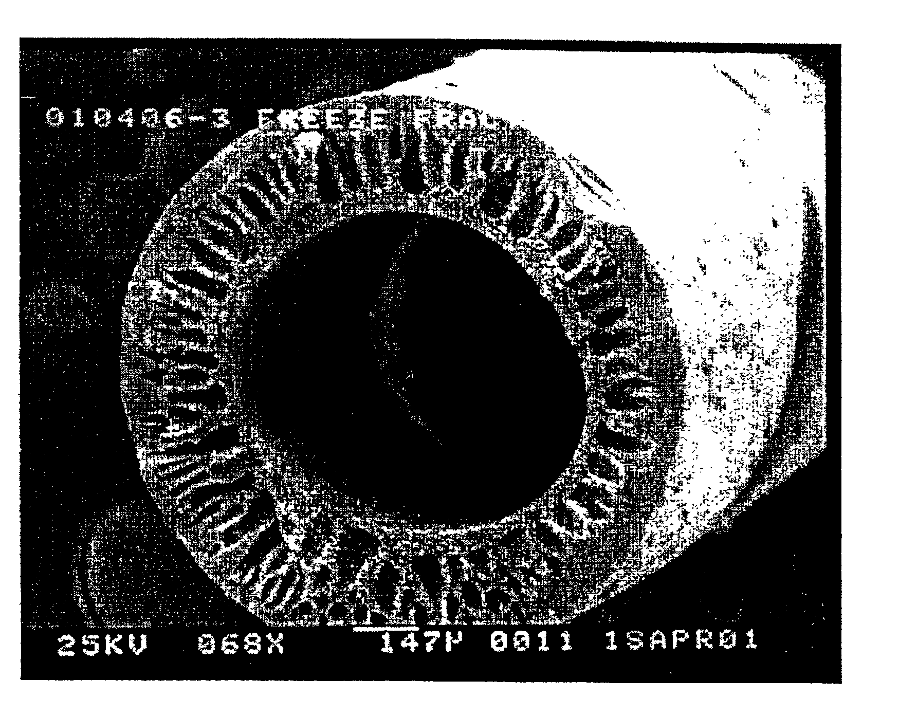
[0012]It is an object of the present invention to provide a hollow fiber membrane that has a narrow pore size distribution and a method of making this membrane so that beverages such as juices and wine may be filtered.
[0013]It is another object of the present invention to provide a hollow fiber microfiltration membrane that has excellent mechanical strength so as to improve membrane durability and performance.
[0014]It is still another object of the present invention to provide a method for making a hollow fiber microfiltration membrane that allows the membrane to be produced efficiently on a large production scale.
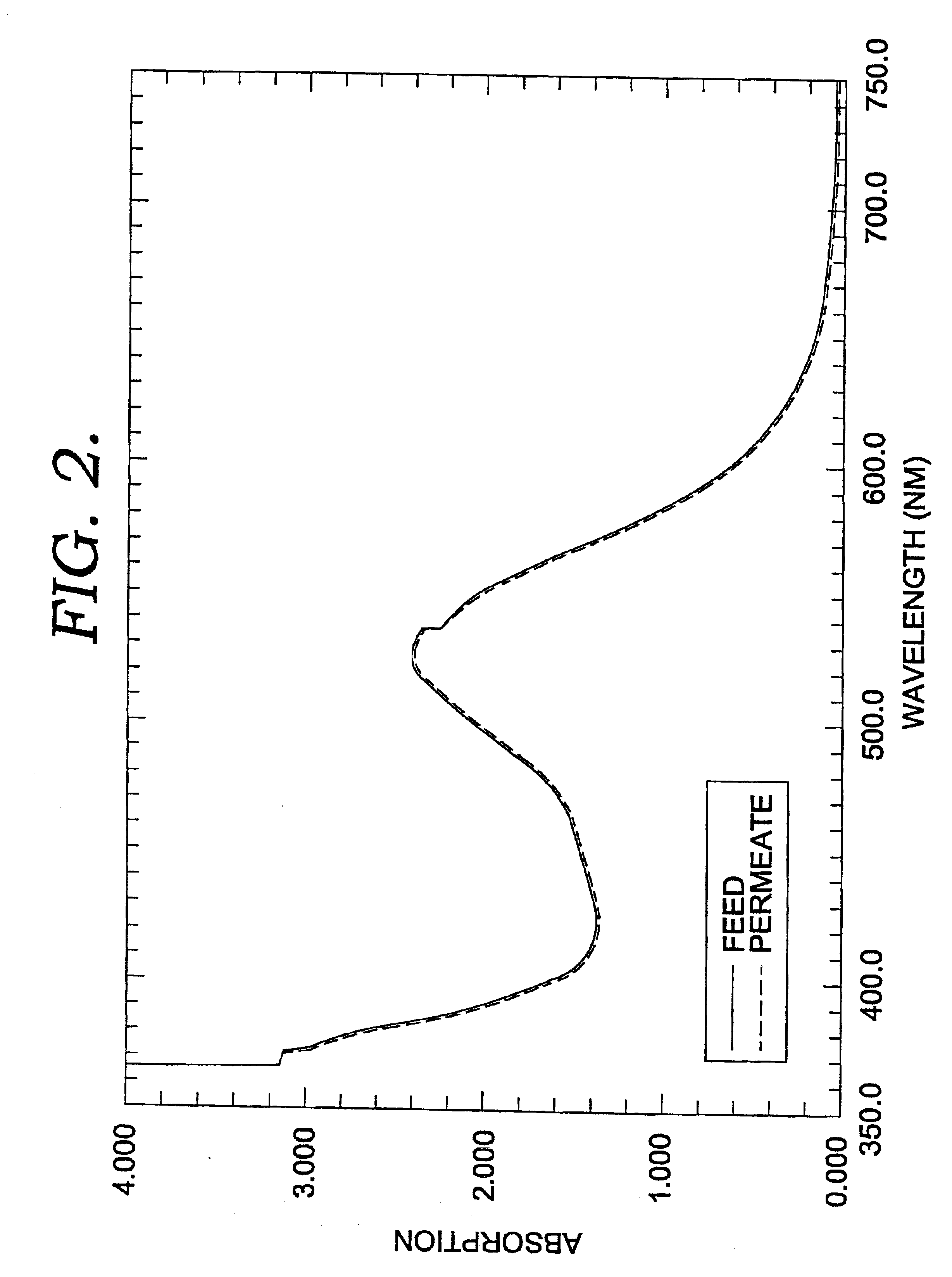
[0015]It is yet another object of the present invention to provide a hollow fiber microfiltration membrane that has a narrow pore size distribution so as to remove bacteria, gel and / or suspended particles from a liquid while allowing the pigment of the liquid to pass through the membrane.

Problems solved by technology

One disadvantage of flat sheet membranes is that they require more volumetric space than a hollow fiber membrane to provide the same filtration surface area.
Unfortunately, it is difficult to make a hollow fiber microfiltration membrane.
The formulation and casting conditions used to obtain a flat sheet microfiltration membrane normally are not applicable for forming a hollow fiber membrane because the viscosity of the casting solution is too low and gravity causes the extruded solution to be broken into pieces.
As such, the broad pore size distribution of the membrane limits its applications due to its poor selectivity.
However, delivery of bore fluid and membrane solution by hydraulic pressure decreases the precision of the delivery of the fluids.
Under these conditions, the hollow fiber membranes obtained also have a broad pore size distribution limiting their applications.
One disadvantage with this method is that the large amount of surfactant used in the casting solution not only slows down the phase inversion rate and productivity but also produces a lot of foam that is difficult to handle on a large production scale.

Method used


Image

  • Hollow fiber microfiltration membranes and a method of making these membranes
  • Hollow fiber microfiltration membranes and a method of making these membranes
  • Hollow fiber microfiltration membranes and a method of making these membranes

Examples


example 1

[0069]In a 2 gallon mixer, 3250 grams of N-methyl-pyrrolidone (NMP) were added to 750 grams of polysulfone (PS) (degree of polymerization was about 1700) and 250 grams of polyvinylpyrrolidone (PVP) while stirring. The mixture was stirred at 60° C. at 1000 rpm until it formed a homogeneous mixture. The mixture was cooled to ambient temperature of about 22° C. Then, 750 grams of maleic anhydride (MA) were added to the mixture. This mixture was stirred at ambient temperature. It formed a homogeneous viscous solution, then it was degassed under a vacuum to give a viscous dope. The dope was transferred to a 5 gallon storage tank and was allowed stand still at ambient temperature for at least 24 hours before use.

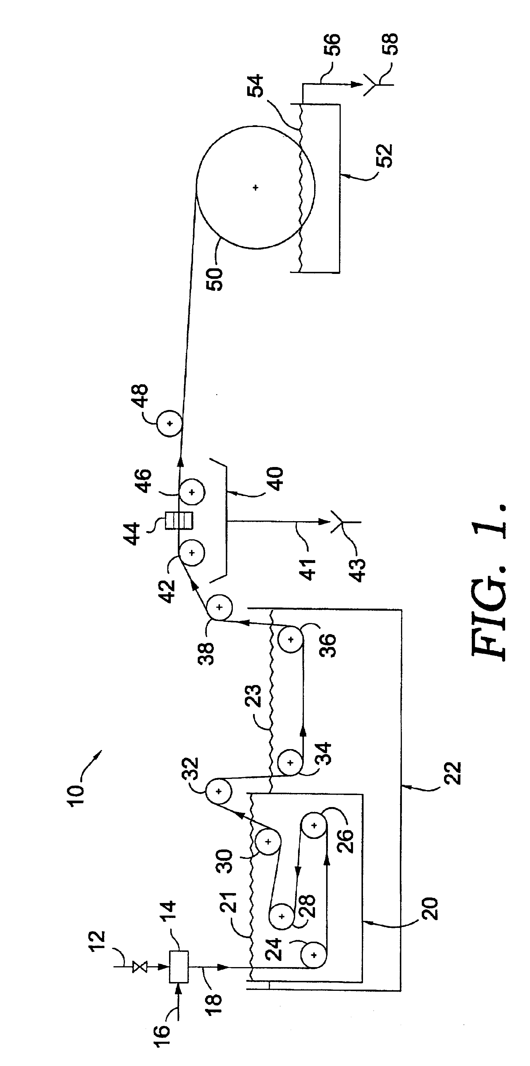
[0070]The dope prepared above was extruded into a hollow fiber using equipment shown in FIG. 1. The fiber spinning conditions used and characteristics of the hollow fiber obtained are shown in Table 1. The dope described above was pressurized into a gear pump and was in turn extru...

example 2

[0076]The same extrusion and spinning conditions as in Example 1 were used to prepare another hollow fiber. The composition of the casting solution was changed, as shown in Table 2. The PVP concentration was increased from 5% by weight to 10% by weight, and the N-methyl-pyrrolidone concentration was lowered by 5% compared with the previous case in Example 1. A solvent mixture, instead of water, was used as a coagulation medium. The water in the coagulation bath was replaced with a solution containing 21.9% by volume N-methyl-pyrrolidone, 21.9% by volume polyethylene glycol, 21.9% by volume isopropylnol and 34.2% by volume water. The fiber spinning conditions used are given in Table 2.

[0077]

TABLE 2Composition of Casting solutionPS1700  15%NMP  60%PVP  10%MA  15%Bore Fluid CompositionNMP33.3%PEG40033.3%IPA33.3%Fiber spinning conditionsDope extrusion rate (ml / min)10Flow rate of bore fluid (water) (ml / min)0.79Fiber spinning speed (ft / min)50Gelation bath temperature (° C.)40Water leachin...

example 3

[0080]The same dope formulation and conditions as in Example 2 were used to prepare a hollow fiber. The total amount of dope mixed was scaled up from 5 kg to 54.48 kg., and a 20 gallon mixer was used to mix the dope. The fiber was spun at 30 ft / min using the equipment shown in FIG. 1. The bore fluid used was the same as in the previous case. An effort was made to eliminate isopropylnol from the coagulation medium because it is flammable and poses a potential danger for a large scale production. The coagulation mixture used was 34% water and 66% N-methyl-pyrrolidone. The fiber spinning conditions used are given in Table 3.

[0081]

TABLE 3Composition of Casting solutionPS1700  15%NMP  60%PVP  10%MA  15%Bore Fluid CompositionNMP33.3%PEG40033.3%IPA33.3%Fiber spinning conditionsDope extrusion rate (ml / min)10Flow rate of bore fluid (water) (ml / min)0.79Fiber spinning speed (ft / min)30Gelation bath temperature (° C.)50Water leaching bath (1) temperature (° C.)50Water leaching bath (2) temperatu...


PUM

PropertyMeasurementUnit
Temperatureaaaaaaaaaa
Lengthaaaaaaaaaa
Lengthaaaaaaaaaa

Abstract

A hollow fiber microfiltration (MF) membrane is provided. The casting solution used to make this membrane includes a fiber-forming polymer having a degree of polymerization greater than about 1000, a water-soluble polymer, an anhydride with about 2 to 12 carbon atoms, and a solvent. The membrane is formed by mixing and heating these components to form a viscous dope and then extruding the dope through an annular orifice to form a hollow fiber MF membrane. The hollow fiber membrane is then fed through a coagulation bath and two leaching baths. The membrane is especially useful for filtering liquids, such as wine and juice, so as to remove bacteria, gel, and solid particles from the liquids.

Description

STATEMENT REGARDING FEDERALLY SPONSORED RESEARCH OR DEVELOPMENT[0001]Not Applicable.CROSS-REFERENCE TO RELATED APPLICATIONS[0002]Not Applicable.BACKGROUND OF THE INVENTION[0003]The present invention relates to a filtration membrane and a method of making this membrane. More specifically, this invention relates to a hollow fiber membrane for use in filtering liquids to remove very large soluble molecules and suspended particles in the liquid.[0004]Membranes are thin-film barriers that allow certain components of a fluid mixture to selectively pass through the membrane while discriminating against other components in the mixture to achieve separation. Membranes are typically formed from polymers and are semi-permeable. The specific physical shape or form of a membrane can vary and can include flat sheets, tubular membranes, and hollow fibers. The specific use to which a membrane is to be put dictates the form selected for its construction. Membranes in the form of hollow fibers are cu...

Claims


Application Information

Patent Timeline
IPC IPC(8): B01D67/00B01D71/34B01D71/00B01D69/00B01D69/08B01D71/68D01D5/00D01D5/24B01D69/02B01D71/16B01D71/26B01D71/56D01F6/76
CPCB01D67/0011B01D67/0016B01D69/08D01D5/24B01D71/68B01D71/34B01D2323/06B01D2323/12B01D67/00165
Inventor JI, JIANGDICECCA, CANDELOROSCHULZ, EDWARD M.MEHTA, MAHESHSTEAD, DAVIDMCKINLEY, DAVIDKOCH, DAVID H
Owner KOCH MEMBRANE SYST
Learn More