Medical imaging device for providing an image representation supporting in positioning an intervention device

a technology of medical imaging and positioning device, which is applied in the field of medical imaging device, can solve the problems of poor contrast, difficult to determine the position of the intervention device relative to the patient's anatomy, and difficult observation of the anatomy of the patient, and achieve the effect of significantly reducing the overall x-ray dose transmitted through the patien

Active Publication Date: 2017-07-11
KONINKLJIJKE PHILIPS NV
View PDF33 Cites 3 Cited by
  • Summary
  • Abstract
  • Description
  • Claims
  • Application Information

AI Technical Summary

Benefits of technology

[0021]The proposed medical imaging device combines two main features for providing an informative image representation indicating the location of an intervention device within a region of interest and thereby helping a surgeon to correctly position the intervention device:
[0022](a) the location of the intervention device may be continuously tracked and an X-ray image acquiring mode may be adapted depending on the current location of the intervention device. Therein, live anatomy images are acquired and a location of the intervention device within a respective live image is determined. Based on such determined location of the intervention device, the settings of a collimator device such as an X-ray absorbing shutter or an X-ray attenuating wedge arrangement may be adjusted. In other words, for example the position of a shutter or of wedges of the collimator device may be set such that an acquisition of a subsequent live anatomy image is restricted to a partial area of the region of interest adjacent to the determined location of the intervention device. In accordance with such restriction, only a partial area of the region of interest is subjected to X-rays for acquiring the subsequent live images. Accordingly, an overall X-ray dose transmitted through the patient may be significantly reduced.
[0024]Therein, it may be beneficial that the pre-live anatomy image(s) may be acquired with a higher image contrast than in the live anatomy images. For example, the pre-live anatomy image may be an angiography image which is acquired with a relatively high X-ray dose and while an X-ray absorbing contrast medium is present within the region of interest. The live anatomy images may be acquired as fluoroscopy images during the intervention procedure without the presence of contrast medium. Therein, an overall X-ray dose may be significantly reduced due to continuous tracking of the current location of the intervention device and adjusting settings of the collimator device such that the live images are acquired only in a restricted area adjacent to such current location of the intervention device.
[0026]With such technique, an overall radiation dose may be reduced by limiting the live image acquisition to the actual area surrounding the intervention device while restoring the occluded anatomy background with pre-live, possibly richer content previously acquired and possibly acquired in diagnostic conditions.

Problems solved by technology

Furthermore, X-ray fluoroscopy images may suffer from a poor contrast such that the patient's anatomy may be difficult to observe in such fluoroscopy images and it may be difficult to determine where the intervention device is positioned relative to the patient's anatomy.

Method used


Image

  • Medical imaging device for providing an image representation supporting in positioning an intervention device
  • Medical imaging device for providing an image representation supporting in positioning an intervention device
  • Medical imaging device for providing an image representation supporting in positioning an intervention device

Examples


Embodiment Construction

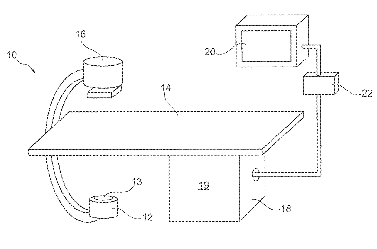
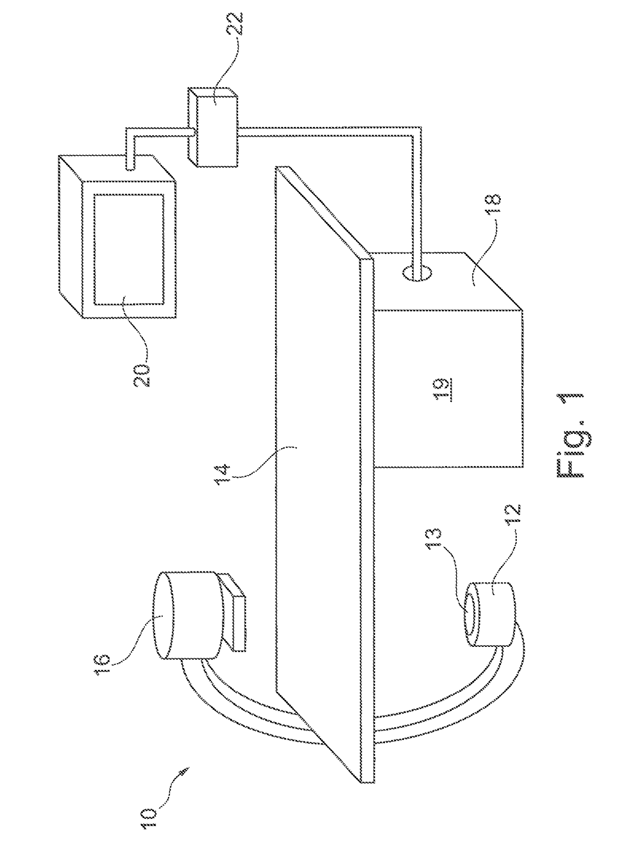
[0032]FIG. 1 schematically shows an X-ray medical imaging system 10 which may be used during an intervention procedure to provide an image representation thereby supporting a surgeon in positioning an intervention device within a patient in accordance with an embodiment of the present invention.

[0033]The imaging system 10 comprises an X-ray image acquisition device with an X-ray source 12 provided to generate X-ray radiation. The X-ray source 12 comprises a collimator 13 including shutters and wedges (not shown) in order to collimate the X-radiation onto a region of interest. A table 14 is provided to receive a patient to be examined. Furthermore, an X-ray image detection module 16 is located opposite to the X-ray source 12. During an imaging procedure, the patient is located on the table 14, i.e. between the X-ray source 12 and the detection module 16. X-rays are emitted by the X-ray source 12 and transmitted through the patient before being detected by the detection module 16.

[003...


PUM


Abstract

A medical imaging device and a method for providing an image representation supporting positioning of an intervention device such as a wire tip (4) in a region of interest during an intervention is proposed. Therein, the following process steps are to be performed: (S1) acquiring a pre-live anatomy image (1) including a region of interest; (S2) acquiring a live anatomy image using a live image acquisition device comprising an adjustable collimator device; (S3) identifying a location (5) of the intervention device (4) within the live anatomy image; (S4) adjusting settings of the collimator device based on the identified location of the intervention device for subsequently acquiring a further live anatomy image representing the region of interest using the live image acquisition device with the collimator device being in the adjusted settings; and providing (S5) the image representation by merging information from the live anatomy image into the pre-live anatomy image. Thereby, the intervention device may be continuously tracked and the collimator device may restrict a field of view to a location of the intervention device thereby significantly reducing an applied X-ray dose. Background anatomical information may be introduced into the final image representation using the pre-live anatomy image possibly having a higher image contrast than the live anatomy images.

Description

CROSS-REFERENCE TO PRIOR APPLICATIONS[0001]This application is the U.S. National Phase application under 35 U.S.C. §371 of International Application Serial No. PCT / IB2012 / 051021, filed on Mar. 5, 2012, which claims the benefit of European Application Serial No. 11305285.6, filed on Mar. 15, 2011. These applications are hereby incorporated by reference herein.FIELD OF THE INVENTION[0002]The present invention relates to a medical imaging device which may be used for providing an image representation supporting in positioning of an intervention device in a region of interest during a medical intervention procedure. Furthermore, the present invention relates to a medical imaging system, a medical imaging method, a computer program and a computer-readable medium, all of which are adapted for providing an image representation which may be used in supporting for example a surgeon during positioning of a medical intervention device.BACKGROUND OF THE INVENTION[0003]During medical interventio...

Claims


Application Information

Patent Timeline
Patent Type & Authority Patents(United States)
IPC IPC(8): G06K9/00A61B90/00A61B6/06A61B5/00A61B6/12A61B6/00
CPCA61B5/0037A61B90/37A61B6/06A61B6/12A61B6/487A61B6/5229A61B6/4441A61B6/481A61B6/503A61B6/504A61B6/542
Inventor FLORENT, RAOULHOORNAERT, BART PIERRE ANTOINE JOZEFSTEGEHUIS, HERMAN
Owner KONINKLJIJKE PHILIPS NV
Why Eureka
Try Eureka