

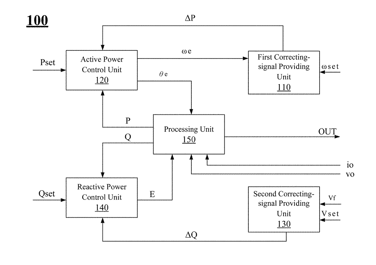
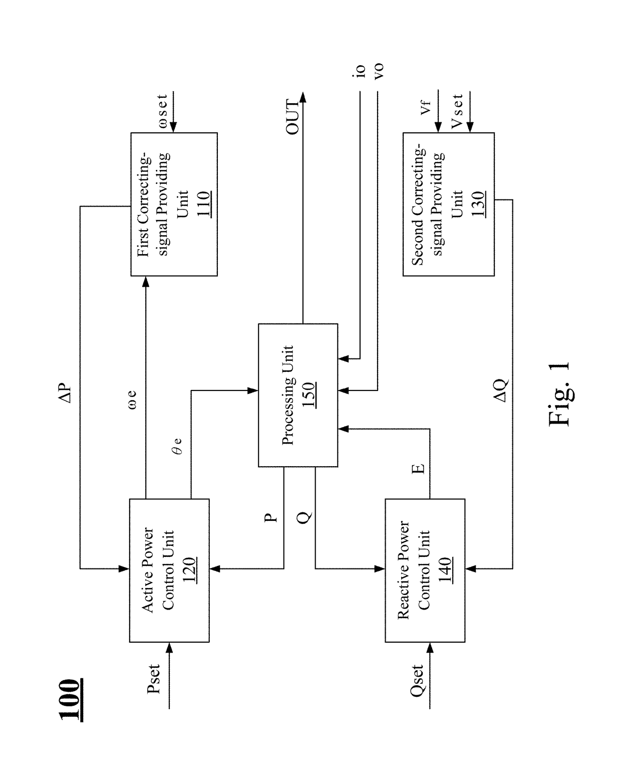
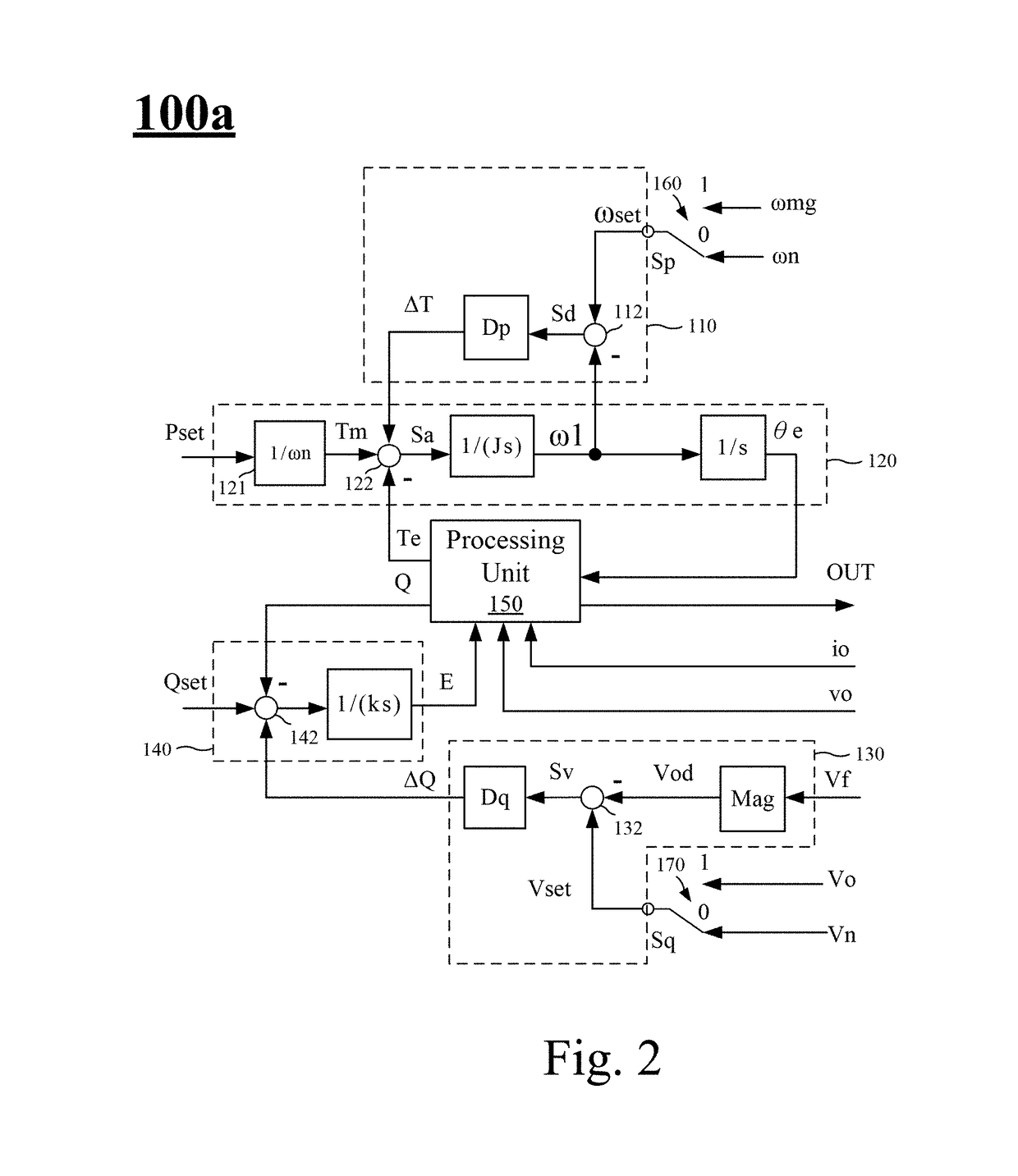
Control signal generating system and inverter control device thereof for improving grid stability
a control signal and signal generation technology, applied in power conversion systems, ac network circuit arrangements, electrical apparatus, etc., can solve problems such as increased control complexity, unstable phenomenon, and no longer ideal voltage sources for grids, and achieve the effect of improving grid stability
- Summary
- Abstract
- Description
- Claims
- Application Information
AI Technical Summary
Benefits of technology
Problems solved by technology
Method used
Image

Examples
Embodiment Construction
[0041]The detailed description provided below in connection with the appended drawings is intended as a description of the present examples and is not intended to represent the only forms in which the present example may be constructed or utilized. The description sets forth the functions of the example and the sequence of steps for constructing and operating the example. However, the same or equivalent functions and sequences may be accomplished by different examples.
[0042]Unless otherwise defined herein, scientific and technical terminologies employed in the present disclosure shall have the meanings that are commonly understood and used by one of ordinary skill in the art. Unless otherwise required by context, it will be understood that singular terms shall include plural forms of the same and plural terms shall include the singular.
[0043]As used herein, “couple” refers to direct physical contact or electrical contact or indirect physical contact or electrical contact between two...
PUM
 Abstract
Description
Claims
Application Information