Digital phase locked loop and method of driving the same

a digital phase and locking loop technology, applied in the direction of electrical equipment, push automatic control, etc., can solve the problems of difficult to apply an analog circuit to cmos manufacturing technology, operating voltage decrease, and difficult to integrate the charge pump pll. to achieve the effect of reducing spurious nois

Inactive Publication Date: 2017-07-11
ELECTRONICS & TELECOMM RES INST
View PDF22 Cites 11 Cited by
  • Summary
  • Abstract
  • Description
  • Claims
  • Application Information

AI Technical Summary

Benefits of technology

[0010]Various embodiments of the present disclosure are directed to a digital PLL and a method of dr...

Problems solved by technology

Therefore, it is difficult to integrate the charge pump PLL, implemented as an analog circuit, with a digital baseband signal processing block that uses a digital CMOS manufacturing process.
Further, as CMOS manufacturing process technology ...

Method used


Image

  • Digital phase locked loop and method of driving the same
  • Digital phase locked loop and method of driving the same
  • Digital phase locked loop and method of driving the same

Examples


Embodiment Construction

[0042]Hereinafter, embodiments will be described in greater detail with reference to the accompanying drawings. Embodiments are described herein with reference to cross-sectional illustrations that are schematic illustrations of embodiments (and intermediate structures). As such, variations from the shapes of the illustrations as a result, for example, of manufacturing techniques and / or tolerances, are to be expected. Thus, embodiments should not be construed as limited to the particular shapes of regions illustrated herein but may include deviations in shapes that result, for example, from manufacturing. In the drawings, lengths and sizes of layers and regions may be exaggerated for clarity. Like reference numerals in the drawings denote like elements.

[0043]Terms such as ‘first’ and ‘second’ may be used to describe various components, but they should not limit the various components. Those terms are only used for the purpose of differentiating a component from other components. For...


PUM


Abstract

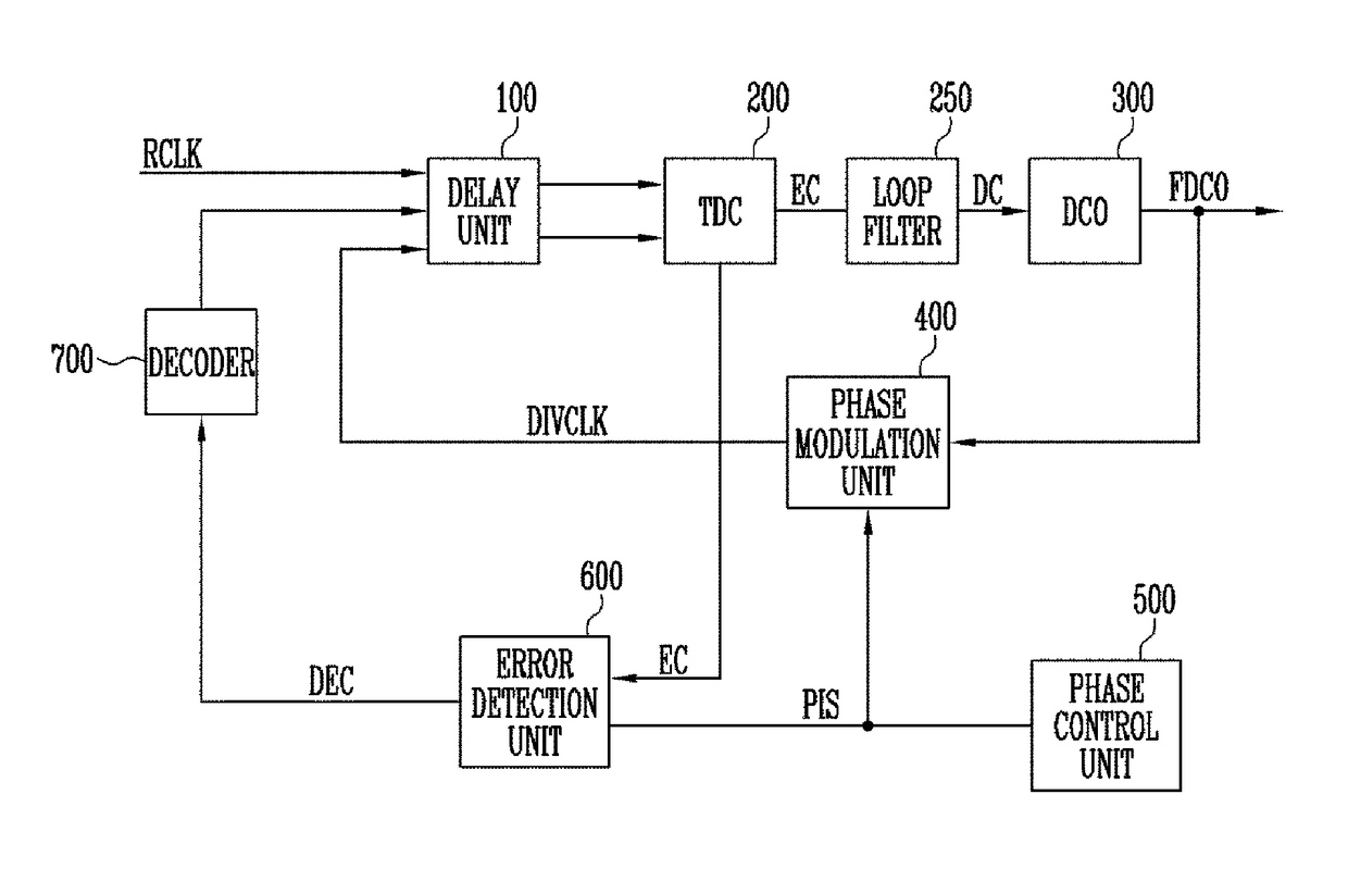
Provided herein is a digital PLL, which can minimize spurious noise. The digital PLL includes a digital controlled oscillator configured to generate an output oscillation signal in response to a digital code, a phase modulation unit configured to perform phase interpolation on the output oscillation signal in response to a phase control code, a TDC configured to generate an error code using a time difference between a reference clock signal and a modulated clock signal, an error detection unit configured to generate a delay code required to compensate for a phase shift error in response to the phase control code and the error code, a delay unit configured to delay at least one of the reference clock signal and the modulated clock signal and provide a delayed clock signal, and a first decoder configured to control the delay unit in response to the delay code.

Description

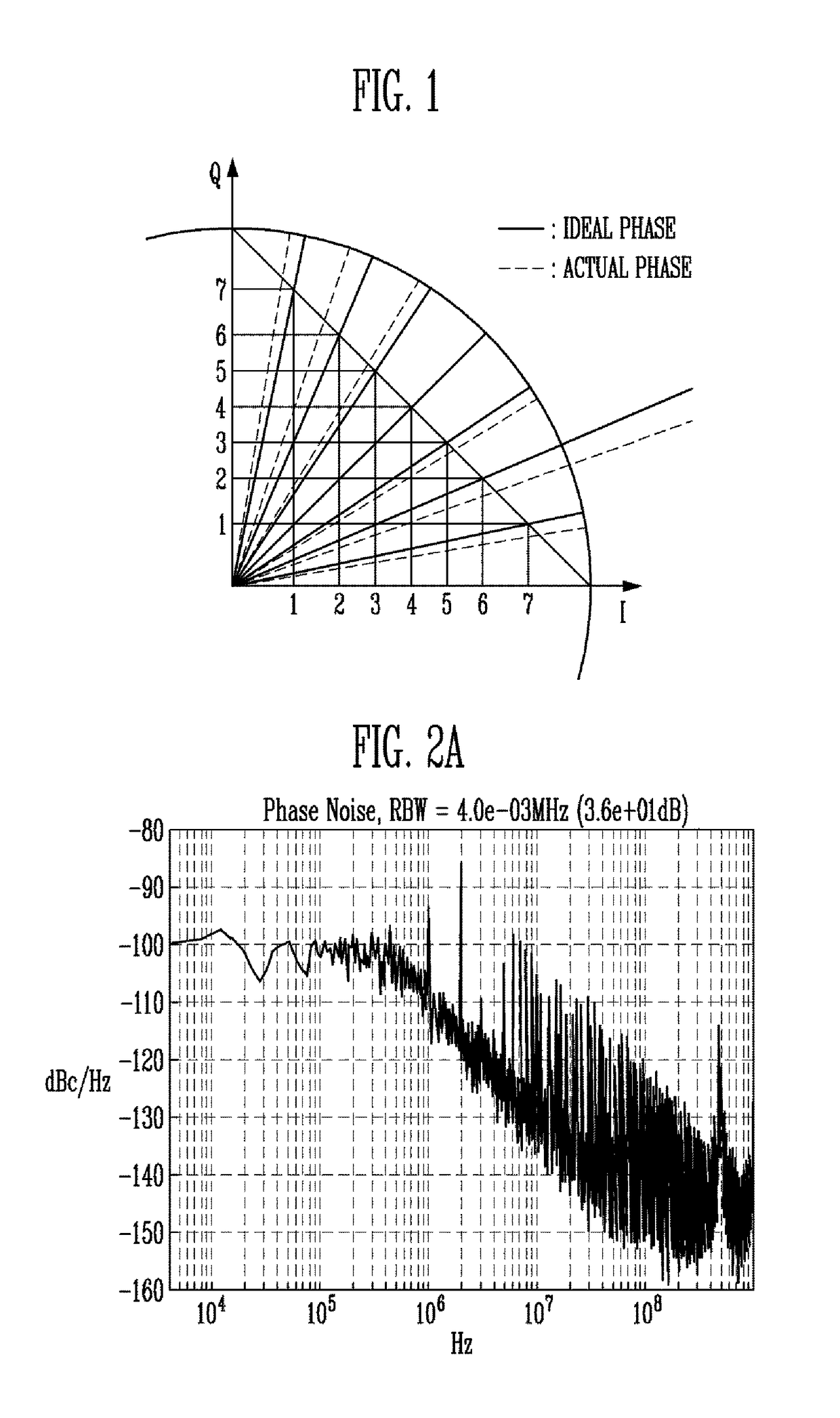
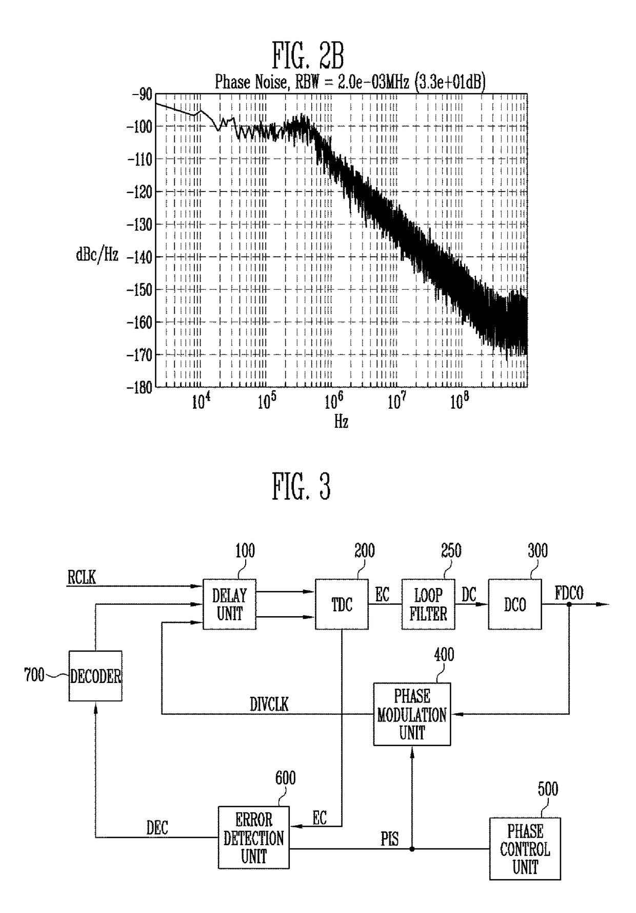
CROSS-REFERENCE TO RELATED APPLICATION[0001]The present application claims priority to Korean patent application number 10-2016-0003157 filed on Jan. 11, 2016, the entire disclosure of which is incorporated herein in its entirety by reference.BACKGROUND[0002]Field of Invention[0003]Various embodiments of the present disclosure relate to a digital phase locked loop (PLL) and a method of driving the digital PLL, and more particularly, to a digital PLL and a method of driving the digital PLL, which can minimize spurious noise.[0004]Description of Related Art[0005]A Charge pump phase locked loop (hereinafter referred to as “PLL”) has been chiefly used so as to implement a radio frequency (RF) synthesizer for multi-band mobile communication. Such a charge pump PLL is implemented as an analog circuit.[0006]When a charge pump PLL is implemented as an analog circuit, a separate analog / RF library is required in addition to a design library, which is provided by a standard digital CMOS manufa...

Claims


Application Information

Patent Timeline
IPC IPC(8): H03L7/099H03L7/18H03L7/085H03L7/093H03L7/091
CPCH03L7/0991H03L7/18H03L7/091H03L7/093H03L7/085H03L7/081H03L7/183
Inventor LEE, JA YOLLEE, MIN JAEKIM, CHEON SOOHEO, MIN UK
Owner ELECTRONICS & TELECOMM RES INST
Why Eureka
Try Eureka